


Input / Output 4-19MN1903
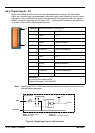
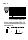
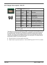
4.5.5 Stepper drive outputs - X10, X11
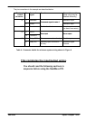
Location Connectors X10, X1 1
Pin X10 Name X11 Name Description
1 Step0+ Step2+ Step signal
2 Dir0+ Dir2+ Direction signal
3 GND GND Signal ground
4 Dir1+ Dir3+ Direction signal
5 Step1+ Step3+ Step signal
6 Step0- Step2- Step signal complement
7 Dir0- Dir2- Direction signal complement
8 Dir1- Dir3- Direction signal complement
9 Step1- Step3- Step signal complement
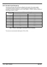
Description
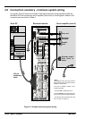
Four sets of stepper motor control outputs available on two 9-pin female
D-type connectors
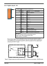
The stepper drive outputs can operate at up to 3MHz. The signals from the NextMove PCI are
at TTL levels but are converted to 5V differential drive signals by a circuit board mounted on
the breakout module. The 9-pin D-type connectors provide 360° shielding when using high
step rates. The outputs can be connected directly to drives with single ended logic inputs by
connecting the complement of the differential signal to the drive ground. The outputs may be
programmed in MintMT for the following functions:
H Step and direction for driving stepper motor drives.
H Digital outputs for general purpose use. See the MintMT keyword STEPPERIO for details.
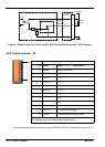
1 5
6 9