


Input / Output 4-15MN1903
4.5 Other I/O
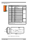
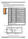
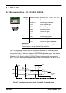
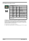
4.5.1 Encoder interfaces - X12, X13, X14, X15, X16
Location Breakout module, connectors X12, X13, X14, X15, X16
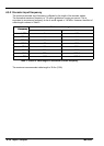
Pin Name Description
1 Encoder V+ Power supply to encoder
2 CHZ+ Index channel signal
3 CHB- Channel B signal complement
4 Shield Shield connection
5 CHA+ Channel A signal
6 CHZ- Index channel signal complement
7 GND Power supply ground
8 CHB Channel B signal
9 CHA- Channel A signal complement
Description
Five identical encoder inputs, each with complementary A, B and Z
channel inputs on a 9-pin female D-type connector
Up to five incremental encoders may be connected to NextMove PCI. Each input channel
uses a MAX3095 differential line receiver with pull up resistors and terminators. Encoders
must provide either 5V dif ferential signals or RS422/RS485 differential signals. The maximum
input frequency is 7.5 million quadrature counts per second. This is equivalent to a maximum
frequency for the A and B signals of 1.87MHz. The shell of the connector is connected to
pin 4. The use of individually shielded twisted pair cable is recommended. See section 4.5.3
for details of the encoder power supply.
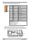
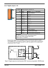
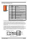
CHA-
CHA+
Encoder
input
circuit
Vcc
NextMove PCI
MAX3095
10R
10R
150R 3k3
3k3
Breakout
module
5
9
100
pin
cable
X12
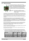
Figure 7 - Encoder channe l input circuit - Encoder C, Channel A shown
15
69