


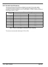

4-24 Input / Output MN1903
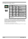
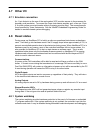
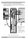
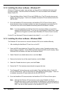
4.9 Connection summary - minimum system wiring
As a guide, Figure 9 shows an example of the typical minimum wiring required to allow the
NextMove PCI and a single axis servo amplifier (motor drive) to work together. Details of the
connector pins are shown in Table 4.
NextMove PCI
100-pin
connecting
cable
Host PC Breakout module Servo amplifier (axis 0)
Encoder output
from drive or
motor
Error out
Gnd*
Enable*
Demand -
Demand +
X7
X8
X12
X1
*Note:
This diagram shows the relay contacts
beingused asa switchacross theservo
amplifier’s enable input.
If the servo amplifier requires a 24V
enable si gnal then:
- Connect Gnd to CGND (X8 pin 9).
-ConnectEnabletoonesideoftherelay
(X8 pin5 fornormally closed operation).
- Connect theother side ofthe relay (X8
pin7)toUSRV+(X8pin8).
Figure 9 - Example minimum system wiring