


Input / Output 4-21MN1903
H Terminators must only be fitted at both ends of the network, not at intermediate nodes.
H The 0V connection of all of the nodes on the network must be tied together through the
CAN cabling. This ensures that the CAN signal levels transmitted by NextMove PCI or
CAN peripheral devices are within the common mode range of the receiver circuitry of
other nodes on the network.
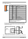
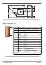
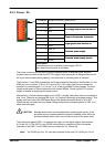
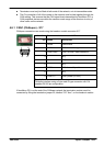
4.6.1 CAN1 (CANopen) - X17
CANopen connections are made using the breakout module connector X17.
Location
Breakout module, connector X17
Pin Name Description
1 Shield Cable shield
2 CAN1- CAN channel 1 negative
3 CAN1 GND CAN1 Ground / earth reference
4 - (NC)
5 - (NC)
6 - (NC)
7 CAN1+ CAN channel 1 positive
8 - (NC)
9 CAN1 V+ CAN1 power (12-24V)
Description
CANopen interface using a 9-pin male D-type connector with CiA
standard DS102 pin configuration
If NextMove PCI is at the end of the CANopen network the termination resistor must be
connected by fitting the termination jumper J8, labelled “CO Term”, on the breakout module.
1 5
6 9