


Input / Output 4-11MN1903
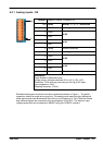
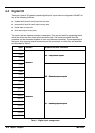
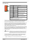
The inputs are conditioned using low pass RC filters and Schmitt trigger buffers. If an input is
configured as edge triggered, the triggering pulse must have a duration of at least 1ms (one
software scan) to guarantee acceptance by MintMT. Voltages below 2V are considered as 0V.
The use of shielded cable for inputs is recommended.
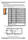
Active high: The digital inputs will be active when a voltage of +24VDC (±20%) is applied to
them and will sink a maximum of 8mA each.
Active low: The digital inputs will be active when grounded (<2V) and will source a maximum
of 8mA each.
Note: Sustained input voltages above 28V will damage the inputs.
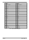
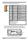
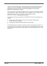
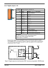
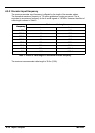
4.4.2 Digital inputs - X2
Location Breakout module, connector X2
Pin Name MintMT keyword /
description
Common
1 Shield Shield connection
2 DIN4 INX.4
3 DIN5 INX.5
C
o
m
m
o
n
1
4 DIN6 INX.6
C
ommon
1
5 DIN7 INX.7
6 DIN8 INX.8
7 DIN9 INX.9
C
o
m
m
o
n
2
8 DIN10 INX.10
C
ommon
2
9 DIN11 INX.11
10 Shield Shield connection
11 Common1 Common connection
12 Common2 Common connection
Description
Eight general purpose optically isolated AC digital inputs.
The inputs are electrically identical to inputs DIN12 to DIN19 described in section 4.4.1.
1
12