


4-18 Input / Output MN1903
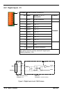
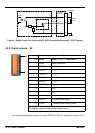
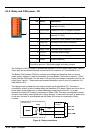
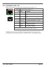
4.5.4 Relay and CAN power - X8
Location Breakout module, connector X8
Pin Name Description
1 CAN1 V+ Power input for CAN1 (CANopen)
network (12-24V)
2 CAN1 GND Ground for CAN1 (CANopen) network
3 CAN2 V+ Power input for CAN2 (Baldor CAN)
network (12-24V)
4 CAN2 GND Ground for CAN2 (Baldor CAN) network
5 Relay NC Normally closed relay connection
6 Relay NO N ormally open relay connection
7 Relay COM Common relay connection
8 USR V+ Customer power supply
9 CGND Customer power supply ground
10 Shield Shield connection
Description
Connection point for CAN power supply and relay contacts.
The CANopen (CAN1) channel is isolated and requires a 12-24V, 60mA supply (pins 1 and 2).
These pins are connected internally to pins 9 and 3 of connector X17 (see section 4.6.1).
The Baldor CAN channel (CAN2) is normally non-isolated and therefore does not need a
power supply. However, it may be necessary for some Baldor CAN nodes to derive a 12-24V
supply from the CAN cable. For this reason, X8 provides a convenient connection point for the
supply (pins 3 and 4). These pins are connected internally to pins 5 and 4 of connector X18
(see section 4.6.2).
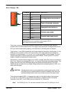
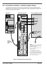
The relay pins are isolated from any internal circuits on the NextMove PCI. The relay is
controlled by a latch, which is cleared when the NextMove PCI resets. Reset can occur due to
power-down, a watchdog error or when deliberately caused by the host PC. In normal
operation the Relay NC contact is connected to Relay COM. The relay is energized in normal
use and is the factory preset global error output channel. In the event of an error or power loss
to the card, the relay is de-energized and the Relay NO contact is connected to Relay
common.
Relay NC
Relay COM
Relay
MintMT
NextMove PCI Breakout
module
Relay NO
5
7
6
X8
100-pin
cable
Figure 8 - Relay conne c tions
1
10