


4-20 Input / Output MN1903
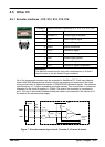
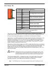
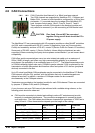
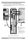
4.6 CAN Connections
CAN (Controller Area Network) is a 1Mb/s local area network.
Two CAN channels are supported by NextMove PCI - CANopen and
Baldor CAN. Access to both channels is configured by a 10-pin 2mm
pin header, J11, mounted along the top edge of the NextMove PCI
card. Jumpers link pin pairs 1 and 2, 3 and 4, 5 and 6, 7 and 8.
These jumpers route the CAN signals to the breakout module and
only need to be removed if you are connecting a CAN Bracket card.
CAUTION: Pins 9 and 10 must NOT be connected
together. Doing so will short-circuit the PC’s
5V power supply.
The NextMove PCI can communicate with I/O expansion modules or other MintMT controllers
via CAN, and is compatible with DS-301, version 4 (Application Layer and Communication
Profile) and mandatory sections of DS-401, version 2 (Device Profile for Generic I/O modules).
Some parts of DS-403, version 1 (Device Profile for Human Machine Interfaces)arealso
supported. When connecting third party devices please contact Baldor if you are unsure about
compatibility.
CAN of fers serial communications over a two wire twisted pair cable up to a maximum of
500m (1640ft) in length, and offers very high communication reliability in an industrial
environment; the probability of an undetected error is 4.7x10
-11
. The default transmission rate
is 125Kbit/s although higher rates up to 1000Kbit/s can be selected. CAN is optimized for the
transmission of small data packets and therefore offers fast update of I/O devices (peripheral
devices) connected to the bus.
Up to 63 mixed type Baldor CAN peripherals may be connected to the NextMove PCI Baldor
CAN network using the CAL protocol, with the limitation that only 4 enabled keypads are
allowed at one time. In addition, a number of CANopen nodes can be connected
simultaneously to the CANopen network.
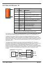
Terminators are provided on the breakout module for each CAN channel. These are connected
by jumpers J7 (Baldor CAN) and J8 (CANopen).
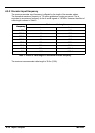
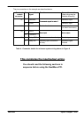
A very low error rate over CAN can only be achieved with a suitable wiring scheme, so the
following points should be observed:
H CAN must be connected via twisted pair cabling to reduce RF emissions and provide
immunity to conducted interference. The connection arrangement is normally a simple
multi-point drop. The CAN cables should have a characteristic impedance of 120Ω and a
delay of 5ns/m. Other characteristics depend upon the length of the cabling:
Cable length
Maximum bit
rate
Resistance Conductor
area
0m ~ 40m (0ft ~ 131ft) 1000Kbit/s <70mΩ/m 0.25 ~ 0.34mm
2
40m ~ 300m (131ft ~ 984ft) 500Kbit/s <60mΩ/m 0.34 ~ 0.60mm
2
300m ~ 600m (984ft ~ 1968ft) 100Kbit/s <40mΩ/m 0.50 ~ 0.60mm
2
600m ~ 1000m (1968ft ~ 3280ft) 50Kbit/s <26mΩ/m 0.75 ~ 0.80mm
2
1&2
3&47&8
5&6