


5-12 Operation MN1903
5.4 Servo axis - testing and tu n in g
This section describes the method for testing and tuning a servo axis. To test a stepper axes,
go straight to section 5.8.
5.4.1 Testing the drive command output
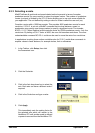
This section tests the operation and direction of the axis command output. It is recommended
that the motor is disconnected for this test.
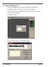
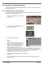
1. Check t hat the Drive enable button is
pressed (down).
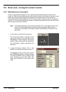
2. In the Toolbox, click Application then click
the Edit & Debug icon.
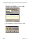
3. Click in the Command window .
4. Type:
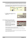
TORQUE.0=5
where 0 is the axis (demand output) to be
tested. In this example, this should cause a
demand of +5% of maximum output (0.5V)
to be produced at the Demand 0 output
(breakout module connector X7, pin 1).
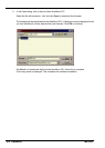
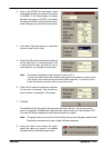
See section 4.3.2 for details of the demand outputs. In WorkBench v5, look at the Spy
window located on the right of the screen. The virtual LED Command display should show
5 (approximately). If there seems to be no command output, check the electrical
connections between the breakout module and the drive.
5. To repeat the tests for negative (reverse) demands, type:
TORQUE.0=-5
This should cause a demand of -5% of maximum output (-0.5V) to be produced at the
Demand 0 output.