128
User-set Allocations Section 5-3
• Areas and Word Ranges for the OUT 1/IN 1 Areas
Step 3: Turn ON the Slave User Allocations Switch
Turn ON the Slave User Allocations Switch (word n+1, bit 11).
Step 4: Turn ON the Slave Enable Switch
Turn ON the Slave Enable Switch (word n+1, bit 06). This will allocated the
above areas as slave areas and the DeviceNet Unit will start slave remote I/O
communications.
Note Once slave communications are enabled by turning ON the Slave Enable
Switch, the Unit will continue to perform slave communications even after the
power is turned OFF and back ON again.
Example Settings for User-set Allocations through Allocated DM Area Words
This example uses the following settings for unit number 0.
• OUT block 1 area and first word: WR (04 Hex), 50 (0032 Hex), 20-byte
size (14 Hex, 10 words)
• IN block 1 area and first word: WR (04 Hex), 100 (0064 Hex), 10-byte
size (0A Hex, 5 words)
Code Name Word range
00 Hex --- The block is not used.
01 Hex CIO Area (CIO) 0000 to 17FF Hex (0 to 6143)
03 Hex DM Area (DM) 0000 to 7FFF Hex (0 to 32767)
04 Hex Word Area (WR) 000 to 01FF Hex (0 to 511)
05 Hex Holding Area (HR) 000 to 01FF Hex (0 to 511)
08 Hex to
14 Hex
Expansion Data Memory (EM)
Bank 0 to C (13 banks)
0000 to 7FFF Hex (0 to 32767) for all
banks
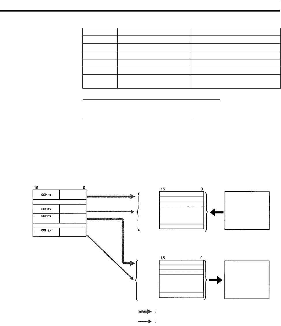
Slave User Allocations Table in the Allocated DM Area Words
Bit
OUT 1
area
First word of the OUT 1 area
OUT 1
area size
IN block 1
area
First word of the IN 1 area
IN 1 area size
Specify the first word.
Specify the size.
Specify the
first word.
Specify the size.
Slave output (OUT) area
Master
OUT area
Bit
First word
specified
Slave input (IN) area
Bit
First word
specified
Master
IN area
Specify the first word.
Specify the size.
to
to
to
to
Word m+8
Word m+9
Word m+10
Word m+11
Word m+12
Word m+13


