46
Nomenclature and Functions Section 2-1
2-1 Nomenclature and Functions
2-1-1 Nomenclature and Functions
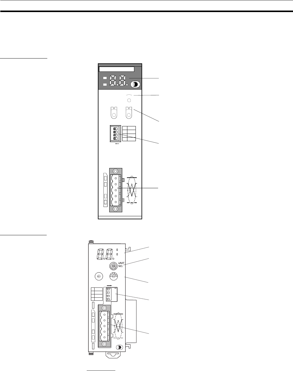
CS1W-DRM21
CJ1W-DRM21
Indicators
The DeviceNet Units are equipped with the following indicators that indicate
the operating status of the node itself and the overall network.
1,2,3... 1. Two status indicators (two-color: Green or red LEDs)
2. A two-digit, 7-segment display
3. Two dot indicators
UNIT
No.
NODE
ADR
ON
DRM21
CS
MS
NS
4
3
2
1
DR0
DR1
ESTP
HOLD
X10
1
9
8
7
6
5
4
3
2
1
0
X10
0
9
8
7
6
5
4
3
2
1
0
F
E
D
C
B
A
9
8
7
6
5
4
3
2
1
0
1234
Indicators
Unit No. switch
This switch sets the unit number of the DeviceNet Unit
as a one-digit hexadecimal value.
Node address switches
These switches set the node address as a two-digit
decimal value.
Communications connector
Connect the Network communications cable to this
connector. The communications power is also
supplied through this connector.
A parallel connector with screws (XW4B-05C1-H1-D)
is provided for node connection.
DIP switch
The pins have the following functions:
Pins 1 and 2: Baud rate
Pin 3: Continue/Stop communications for error
(when used as a Master)
Pin 4: Hold/clear I/O for communications error
(when used as a Slave)
1
1234
2
3
4
HOLD
ON
ESTP
DR1
DR0
DRM21
MS
NS
6
7
8
9
0
1
2
3
4
5
6
7
8
9
N
O
D
E
A
DR
x1
0
0
x1
0
1
ON
Indicators
Unit No. switch
This switch sets the unit number of the DeviceNet Unit as a one-
digit hexadecimal value.
Node address switches
These switches set the node address as a two-digit decimal value.
DIP switch
The pins have the following functions:
Pins 1 and 2: Baud rate
Pin 3: Continue/Stop communications for error (when used as a
Master)
Pin 4: Hold/clear I/O for communications error (when used as a
Slave)
Communications connector
Connect the Network communications cable to this connector. The
communications power is also supplied through this connector.
A parallel connector with screws (XW4B-O5C1-H1-D) is provided
for node connection.


