


12
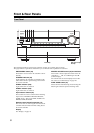
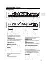
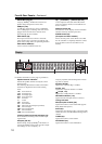
Front & Rear Panels—Continued
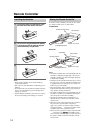
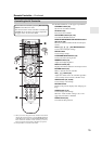
REMOTE CONTROL
This (Remote Interactive) jack can be con-
nected to an jack on another Onkyo AV compo-
nent. The AV controller’s remote controller can then
be used to control that component. To use , you
must make an analog audio connection (RCA)
between the AV controller and the other AV compo-
nent, even if they are connected digitally.
RS232
Terminal for control.
HDMI IN 1–7, OUT MAIN, and OUT SUB
HDMI (High Definition Multimedia Interface) con-
nections carry digital audio and digital video.
The HDMI inputs are for connecting components
with an HDMI output, such as a DVD player, Blu-
ray Disc Player, DVD recorder, or DVR (digital
video recorder). They’re assignable, which means
you can assign each one to an input selector to suit
your setup. See “HDMI Input Setup” on page 49.
The HDMI outputs are for connecting a TV or pro-
jector with an HDMI input.
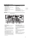
MONITOR OUT
These S-Video and composite video jacks should be
connected to a video input on your TV or projector.
COMPONENT VIDEO IN 1, 2 and 3
These RCA component video inputs are for con-
necting components with a component video out-
put, such as a DVD player, DVD recorder, or DVR
(digital video recorder). They’re assignable, which
means you can assign each one to an input selector
to suit your setup. See “Component Video Input
Setup” on page 50.
COMPONENT VIDEO MONITOR OUT
These RCA component video outputs are for con-
necting a TV or projector with a component video
input.
COMPONENT VIDEO ZONE 2 OUT
This RCA component video output is for connect-
ing a TV or projector with a component video input
located in your main listening room or Zone 2.
ZONE 2 OUT
This composite video output can be connected to a
video input on a TV in Zone 2.
PC INPUT ANALOG RGB
This input terminal is for connecting a personal
computer with an analog RGB output. You can
assign it to an input selector to suit your setup. See
“Component Video Input Setup” on page 50.
FM ANTENNA
This jack is for connecting an FM antenna.
AM ANTENNA
These push terminals are for connecting an AM
antenna.
AC INLET
The supplied power cord is connected here. The
other end of the power cord should be connected to
a suitable wall outlet.
GND screw
This screw is for connecting a turntable’s ground
wire.
PHONO IN
These analog audio inputs are for connecting a turn-
table.
BALANCE L/R INPUT
This balanced XLR input is for connecting a com-
ponent with a stereo balanced XLR output. For a
mono source, connect to the BALANCE L XLR.
CD IN
These analog audio inputs are for connecting a CD
player’s analog audio output.
12V TRIGGER OUT (A/B/C)
These outputs can be connected to the 12-volt trig-
ger inputs on other components.
TV/TAPE IN/OUT
These analog audio inputs and outputs are for con-
necting a TV or recorder with an analog audio input
and output (cassette, Mini Disc, etc.).
AUX 2 IN
This analog audio input is for connecting an analog
audio output, such as an audio device, etc.
GAME IN
Here you can connect a game console, etc. Input
jacks include S-Video, composite video, and analog
audio.
CBL/SAT IN
Here you can connect a cable/satellite receiver, set-
top box, etc. Input jacks include S-Video, composite
video, and analog audio.
VCR/DVR IN/OUT
Here you can connect a VCR or DVR (digital video
recorder). Input and output jacks include S-Video,
composite video, and analog audio.
DVD/BD IN
Here you can connect a DVD/BD player. Input
jacks include S-Video, composite video, and analog
audio. You can connect a DVD/BD player’s 2-chan-
nel analog audio output.
MULTI CH input: FRONT L/R, CENTER,
SUBWOOFER, SURR L/R, and SURR BACK
L/R
This analog multichannel input is for connecting a
component with a 5.1/7.1-channel analog audio out-
put, such as a DVD player, DVD-Audio or Super
Audio CD-capable player, or an MPEG decoder.