50
First Time Setup—Continued
Component Video Input Setup
If you connect to a COMPONENT VIDEO IN or PC
INPUT ANALOG RGB, you must assign it to an input
selector. For example, if you connect your DVD/BD
player to COMPONENT VIDEO IN 2, you should
assign it to the DVD/BD input selector.
If you’ve connected your TV to the AV controller with a
component video cable, you can set the AV controller so
that composite video and S-Video sources are
upconverted* and output by the COMPONENT VIDEO
MONITOR OUT
*1
. You can set this for each input
selector by selecting the “- - - - -” option.
*1 Only when “Monitor Out” setting is set to “Analog”.
Notes:
• For composite video and S-Video upconversion for
the COMPONENT VIDEO MONITOR OUT, the
“Monitor Out” setting must be set to “Analog” (see
page 47), and the “Component Video Input” setting
must be set to “- - - - -”. See page 28 for more
information on video signal flow and upconversion.
• If not connected to the same output you have selected
in the “Monitor Out” setting, the “Monitor Out”
setting will be automatically switched to “Analog”
(see page 47).
• If you connect an input component (such as UP-A1
Dock that seated iPod) to the UNIVERSAL PORT jack,
you cannot assign any input to PORT selector.
• This procedure can also be performed on the AV
controller by using its [SETUP] button, arrow buttons,
and [ENTER] button.
■ About PC Input
Signals from PC INPUT ANALOG RGB are output
from the HDMI output without the resolution
conversion.
Supported Resolution:
• VGA (640 480) 60/72/75/85 Hz
• SVGA (800 600) 56/60/72/75/85 Hz
• XGA (1024 768) 60/70/75/85 Hz
• SXGA (1280 1024) 60/75 Hz
Note:
The picture adjust setting is effective for only 60 Hz.
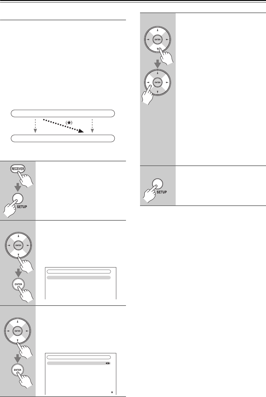
1
Press the [RECEIVER] button fol-
lowed by the [SETUP] button.
The main menu appears onscreen.
If the main menu doesn’t appear, make
sure the appropriate external input is
selected on your TV.
2
Use the Up and Down [ ]/[ ] but-
tons to select “1. Input/Output
Assign”, and then press
[ENTER].
The “Input/Output Assign” menu
appears.
3
Use the Up and Down [ ]/[ ] but-
tons to select “3. Component
Video Input”, and then press
[ENTER].
The “Component Video Input” menu
appears.
IN
OUT
Composite video, S-Video
Composite video, S-Video
Component video
Component video
1. Input/Output Assign
1. Monitor Out
2. HDMI Input
3. Component Video Input
4. Digital Audio Input
5. Analog Audio Input
6. Gamma Curve
1–3. Component Video Input
IN1
- - - - -
IN2
IN3
- - - - -
DVD/BD
VCR/DVR
CBL/SAT
GAME
AUX 1
4
Use the Up and Down [ ]/[ ] but-
tons to select an input selector,
and then use the Left and Right
[ ]/[ ] buttons to select:
IN1: Select if the video component
is connected to COMPO-
NENT VIDEO IN 1.
IN2: Select if the video component
is connected to COMPO-
NENT VIDEO IN 2.
IN3: Select if the video component
is connected to COMPO-
NENT VIDEO IN 3.
PC IN: Select if the personal com-
puter is connected to PC
INPUT ANALOG RGB.
-----: Select if you are using the
HDMI outputs, rather than
the COMPONENT VIDEO
OUT, for the output from
composite video, S-Video,
and component video
sources.
5
Press the [SETUP] button.
The setup menu closes.
×
×
×
×


