


24
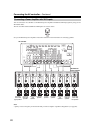
Connecting the AV controller—Continued
• Before making any AV connections, read the manuals
supplied with your other AV components.
• Don’t connect the power cord until you’ve completed
and double-checked all AV connections.
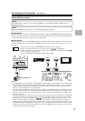
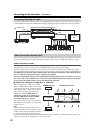
Optical Digital Jacks
The AV controller’s optical digital jacks have shutter-
type covers that open when an optical plug is inserted
and close when it’s removed. Push plugs in all the way.
Caution:
To prevent shutter damage, hold the optical plug straight
when inserting and removing.
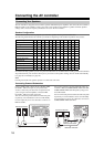
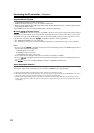
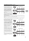
AV Connection Color Coding
RCA-type AV connections are usually color-coded: red,
white, and yellow. Use red plugs to connect right-chan-
nel audio inputs and outputs (typically labeled “R”). Use
white plugs to connect left-channel audio inputs and out-
puts (typically labeled “L”). And use yellow plugs to
connect composite video inputs and outputs.
• Push plugs in all the way to make
good connections (loose connec-
tions can cause noise or malfunc-
tions).
• To prevent interference, keep
audio and video cables away from
power cords and speaker cables.
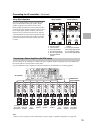
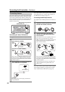
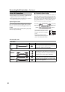
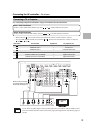
AV Cables & Jacks
About AV Connections
Analog audio
Composite video
Left (white)
Right (red) Right (red)
Left (white)
(Yellow)
(Yellow)
Right!
Wrong!
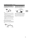
Video / Audio
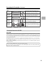
Cable Jack Description
HDMI
HDMI connections can carry uncompressed stan-
dard- or high-definition digital video and audio and
offer the best picture and sound quality.
Video
Component
video cable
Component video separates the luminance (Y) and
color difference signals (P
R, PB), providing the best
picture quality (some TV manufacturers label their
component video sockets slightly differently).
S-Video cable
S-Video separates the luminance and color signals and
provides better picture quality than composite video.
Composite
video cable
Composite video is commonly used on TVs, VCRs,
and other video equipment.
HDMI
Y
P
B/CB
PR/CR
Y
P
B/CB
PR/CR
V