


Page 16 GPS Chart Plotters
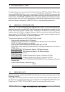
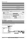
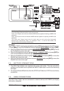
2.4 CONNECTIONS
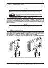
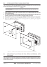
The GPS Chart Plotter has connectors that are used to connect to the power supply, GPS
Antenna (CP180
AND CP300 ONLY) optional FF520 50/200kHz BLACK BOX FISH FINDER
and to NMEA devices such as VHF’s, AIS Receivers, digital instruments and autopilots.
NOTE
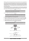
The GPS Chart Plotter can send many sentences to external NMEA devices. The NMEA Output
wires are Yellow, Brown and White. If you have connected devices as shown in the below table and
need to feed NMEA to other devices (Autopilot, RADAR…) you can parallel wires from the Yellow,
Brown or White wires.
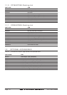
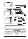
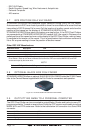
2.4.0 Connection Table For CP180/CP180i
12VDC Power and NMEA PWR & ACC 1 Cable
Pin Wire Color Description Connection Example Additional Comments
1 Black Battery Ground Connect to Battery Ground
2 Red Battery Positive Connect to Battery Positive
3 Green NMEA Common Common (ground) for NMEA devices
4 Blue Port1 Input Connect to Output of NMEA device Default is NMEA0183*
5 Brown Port1 Output Connect to Input of NMEA device Default is NMEA0183 with GLL, RMB, RMC
and XTE sentences
6 Gray Port2 Input Connect to Output of NMEA device Default is NMEA0183**
7 White Port2 Output Connect to Input of NMEA device Default is NMEA0183 with GLL, RMB, RMC
and XTE sentences
8 Yellow Port3 Output Connect to Output of NMEA device Default is NMEA0183 with APA, APB, XTE,
COG and BOD sentences***
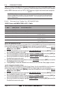
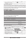
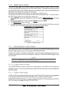
*NOTE: AIS RECEIVER OPTION
When an optional AIS rceiver is connected, Port 1 of the NMEA in/out Communication setup
menu must be changed to AIS 38400 as shown below for communications.
1. From the Chart page, press [MENU]. Move the ShuttlePoint knob to highlight
SETUP
MENU and press [ENT].
2. Move the ShuttlePoint knob to highlight
ADVANCED SETUP and press [ENT] or move
the ShuttlePoint knob to the right.
3. Move the ShuttlePoint knob to highlight
IN/OUT CONNECTIONS and press [ENT] or
move the ShuttlePoint knob to the right.
4. Move the ShuttlePoint knob to highlight
PORT 1 INPUT and press [ENT] or move the
ShuttlePoint knob to the right.
5. Move the ShuttlePoint knob up/down to select
AIS 38400 and press [ENT] or move the
ShuttlePoint knob to the right.
6. Press [CLR] or move the ShuttlePoint knob to the left until the Chart page is shown.
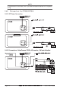
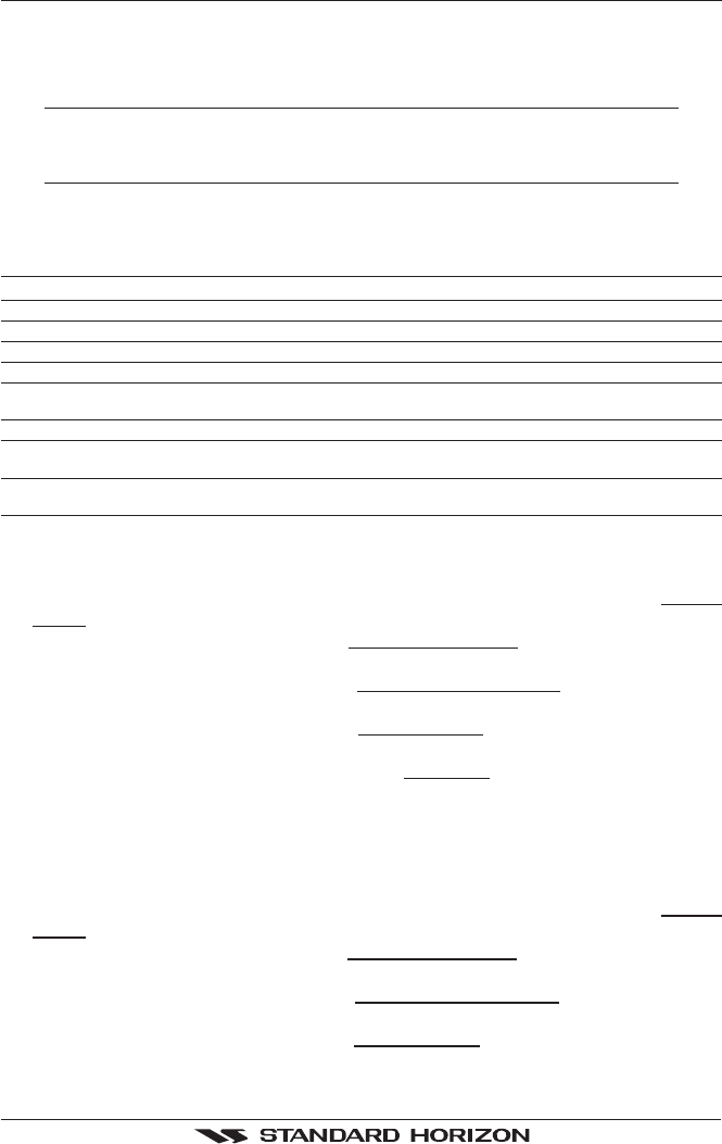
**NOTE: FF520 FISH FINDER OPTION
When a FF520 is connected to the GPS Chart Plotter, Port 2 of the NMEA in/out Communi-
cation setup menu must be changed to FF520 as shown below for communications.
1. From the Chart page, press [MENU]. Move the ShuttlePoint knob to highlight
SETUP
MENU and press [ENT].
2. Move the ShuttlePoint knob to highlight
ADVANCED SETUP and press [ENT] or move
the ShuttlePoint knob to the right.
3. Move the ShuttlePoint knob to highlight
IN/OUT CONNECTIONS and press [ENT] or
move the ShuttlePoint knob to the right.
4. Move the ShuttlePoint knob to highlight
PORT 2 INPUT and press [ENT] or move the
ShuttlePoint knob to the right.