


Page 80 GPS Chart Plotters
To use the TD Coordinate System the user must setup the Chain and Pair information of
the TD’s. If you do not know this information, refer to paper charts that show the Chain and
Pair information.
ASF1/2 : Additional Secondary phase Factor (TD Coordinate System)
Correction to TD1/2 values which can be inserted by the user to take in account the
additional signal propagation delay aver a mixed land/seawater path compared to on all-
seawater path. The user should enter delay values to fine adjust the position calculated.
Alter : Alternate Solution (TD Coordinate System)
Parameter selected by the user that is applied in the conversion of geographical coordinates
Lat/Lon to TD values. To be used if the position displayed is roughly not correct.
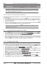
13.2 COMPASS
The GPS Chart Plotter computes compass direction from the constellation of GPS
Satellites. For the GPS Chart Plotter to compute direction the vessel must be moving
through the water. This menu allows the GPS Chart Plotter to customize the following
selections:
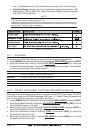
Bearings : Selects between True and Magnetic. When Magnetic bearings is enabled, the GPS Chart Plotter applies
the selected Magnetic Variation (Auto or Manual, see next paragraph) to compute True bearing.
Variation : Allows the user to select Auto or Manual. When Auto mode is selected the GPS Chart Plotter computes
the offset by the current GPS fixed location. Manual mode allows the user to enter in a magnetic variation
that is applied in the True conversion.
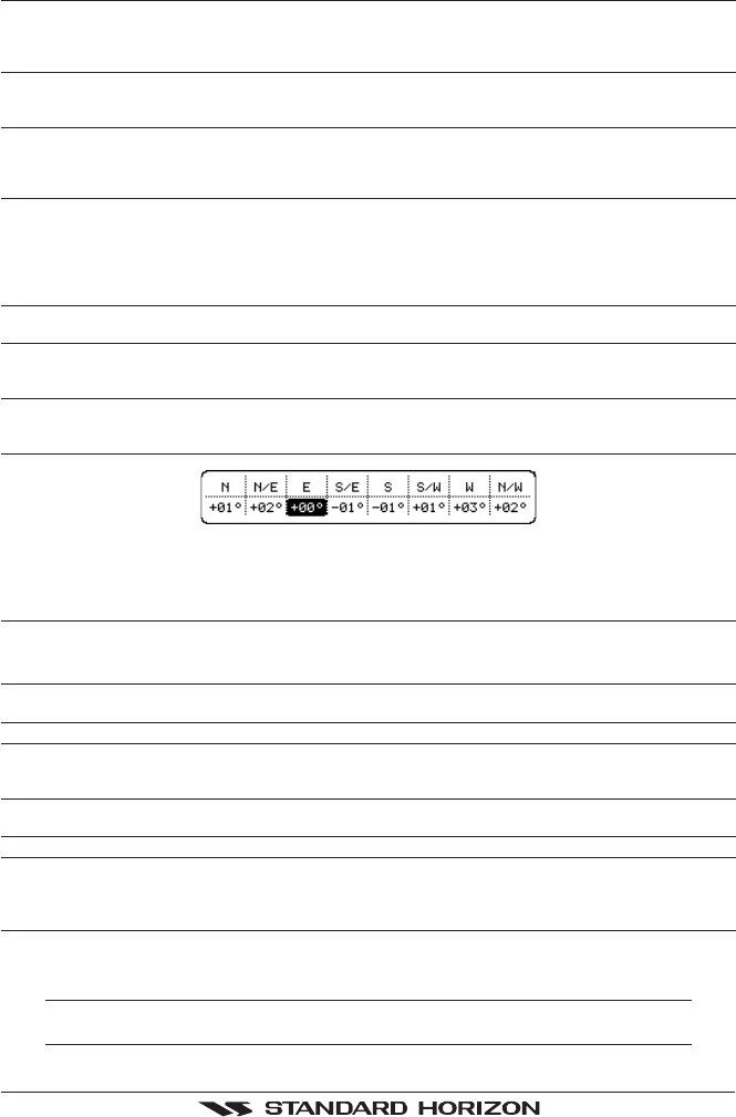
Calibration : This function allows a user to enter in the offset for areas that the vessel may cruise instead of entering
in a manual offset for one location. This offset is useful for cruising vessels or vessels that travel
internationally often.
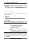
Figure 13.2 - Compass Table
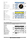
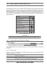
13.3 ALARMS
This menu is used to select and setup audible and visual Alarms. Available alarms are
Arrival, XTE, Depth, Anchor and Grounding Alarm.
Arrival Alarm : Alerts when the vessel is approaching a single destination point or when arriving at a leg in a Route.
Available selections: 0.00 to 9.99NM.
XTE Alarm :Alerts when the vessel is deviating from a defined course. Available selections: 0.00 to 9.99NM.
Depth Alarm :Alerts when the received depth Value from the optional FF520 50/200kHz BLACK BOX FISH
FINDER or Depth Finder inputting NMEA data into the GPS Chart Plotter is lower than the selected
value. Available selections: 0000 to 3000 FT.
Anchor Alarm : Alerts when the ships moves off a selected locations by a selected distance. Available selections:
0.00 to 9.99NM.
Audible Alarm :Enables or disables the alarm beep.
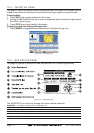
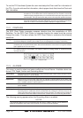
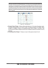
Grounding Alarm :This function looks ahead of the vessels heading to see if a potential danger exists. When the
Grounding Alarm is enabled the GPS Chart Plotter will draw a triangle in front of the vessel on the
Chart page showing the area that is being searched as shown below. The depth and range (distance)
of the area the GPS Chart Plotter looks ahead for a shallow area can be set using this function.
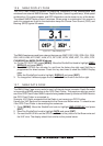
The following warning appears when the Grounding Alarm is enabled:
NOTES
The Grounding Alarm function only operates with the new NT
+
/MAX C-CARDs. It also affects the
speed of the redraw of the screen. If this function is not used it may be disabled.