


Page 18 GPS Chart Plotters
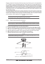
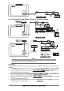
NMEA ACC 2 Cable
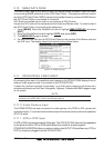
Pin Wire Color Description Connection Example Additional Comments
1 Black NC
2 Red NC
3 Green NMEA Common Common (ground) for NMEA devices
4 Blue Port 4 Input Connect to Output of NMEA device Default is NMEA0183**
5 Brown Port 4 Output Connect to Input of NMEA device Default is NMEA0183 with GLL, RMB, RMC
and XTE sentences
6 Gray Port 5 Input Connect to Output of NMEA device Default is NMEA0183
7 White Port 5 Output Connect to Input of NMEA device Default is NMEA0183 with GLL, RMB, RMC
and XTE sentences
8 Yellow NC
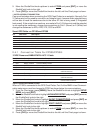
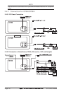
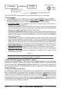
**NOTE: AIS RECEIVER OPTION
When an optional AIS rceiver is connected, Port 4 of the NMEA in/out Communication setup
menu must be changed to AIS 38400 as shown below for communications.
1. From the Chart page, press [MENU]. Move the ShuttlePoint knob to highlight
SETUP
MENU and press [ENT].
2. Move the ShuttlePoint knob to highlight
ADVANCED SETUP and press [ENT] or move
the ShuttlePoint knob to the right.
3. Move the ShuttlePoint knob to highlight
IN/OUT CONNECTIONS and press [ENT] or
move the ShuttlePoint knob to the right.
4. Move the ShuttlePoint knob to highlight
PORT 4 INPUT and press [ENT] or move the
ShuttlePoint knob to the right.
5. Move the ShuttlePoint knob up/down to select
AIS 38400 and press [ENT] or move the
ShuttlePoint knob to the right.
6. Press [CLR] or move the ShuttlePoint knob to the left until the Chart page is shown.
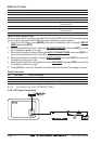
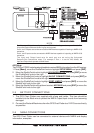
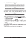
Video Connector
Pin Description Connection Example
1 Ground Connect to Video Signal Ground of DVD/VCR/Video Cameras
2 + 9 / 12 VDC Connect to Video Cameras Power Input
3 Video Signal + Connect to NTSC Video Signal + of DVD/VCR/Video Cameras
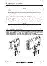
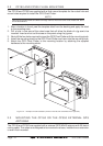
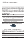
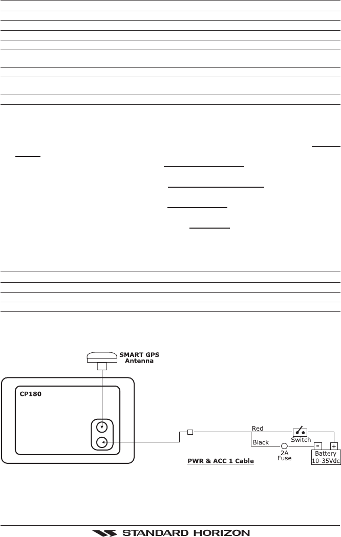
2.4.2 Connection For CP180/CP180i
2.4.2.1 DC Power Connection