


Page 14 CP500
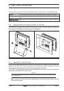
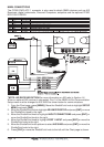
2. Drill a hole in one area of the cutout area that will allow the blade of a jigsaw to be
inserted. Insert and cut out the area on the panel using the jigsaw.
3. Next drill the four holes required to insert the GPS Chart Plotter with the mounting studs.
4. Install the mounting studs on the GPS Chart Plotter and insert into the mounting hole.
5. Attach the GPS Chart Plotter to the mounting location by attaching the supplied
hardware to the mounting studs.
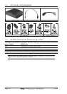
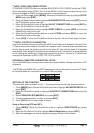
2.3 EXTERNAL GPS ANTENNA MOUNTING
The CP500 is supplied with a external GPS WAAS antenna with 15 meter of routing cable.
This antenna is designed to be mounted on a base, installed on an extension or even flush
mounted.
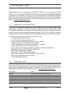
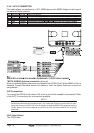
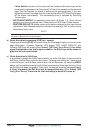
GPS Flush Mount Holes
GPS Base Mount
GPS Flush Mount
Ø8 mm [0.31"]
Ø3.2mm
[0.13
”]
GPS OVERALL SHAPE
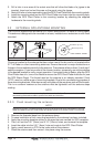
Choose a location for the antenna that has a clear view of the sky and is not located within
3 FT of Radar or other transmitting antennas. Ensure there are no major obstructions or
fixtures in the immediate proximity to the antenna. The antenna relies on direct “line of sight”
satellite reception. If you are unsure of the chosen location, temporarily mount the antenna
in the desired location to verify correct operation. If mounted close to Radar, after the GPS
Chart Plotter has a fix, turn on the Radar to ensure the GPS Chart Plotter holds the fix (use
the GPS Status Page). The thread used on the antenna is an industry standard (1inch
14TPI) used on a wide range of mounting brackets. Due to the manufacturing process of
these mounting brackets, the antenna may not tighten all the way down onto all the threads.
This is no concern however as the antenna must be tightened until the antenna stops
rotating.
NOTE
The antenna cable can be cut and spliced to ease installation. Care must be taken when
reconnecting the antenna cable to protect from water and corrosion.
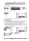
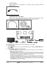
2.3.0 Flush mounting the antenna
NOTE
Before drilling holes, it is recommended the antenna be positioned where the location is planned,
cable connected to the GPS Chart Plotter and power turned On to ensure a GPS Fix is received.
1. Remove the threaded base from the antenna dome.
2. To ease installation a flush mounting template for the antenna has been included.
3. Apply the mounting template sticker to the area that was verified for GPS reception.
4. Then, drill out the 0.31” (8mm) and 0.13” (3.2mm) holes, and remove the template.
5. Insert the cable into the 0.31” (8mm) hole and route to the GPS Chart Plotter.
6. Apply a small amount or RTV to the under side of the antenna.
7. Place the antenna and then screw it into place using the screws.