


CP500 Page 15
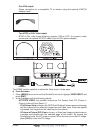
NOTE
In some cases the screw may not be long enough, if this happens simply apply more RTV to the
underside of the antenna to glue it into place.
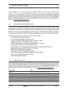
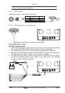
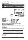
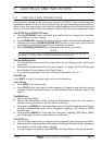
2.3.1 GPS cable
The following table is to be used as a reference.
1
2
3
4
5
6
+10-35 Vdc
GPS RX+
GPS TX+
GND/COMMON
RED
GREEN
BROWN
BLACK/YELLOW/SHIELD
CABLE,
Wire Color
FUNCTION
1
2
3
6
CONNECTOR,
6pins
SMART GPS
SENSOR
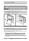
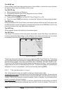
2.3.2 GPS antenna connections
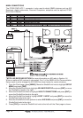
2.3.2.0 PWR & ACC 1 Cable
BATTERY CONNECTIONS
1. The CP500 is supplied with a fuse and holder. This fuse should be installed into the Black
wire to protect the NMEA Output/Input circuits from becoming damaged.
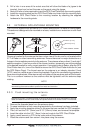
2. Two Accessory cables (exactly the same cable) are supplied with the CP500.
3. Connect one of the Accessory cables to the PWR ACC 1 connector on the rear panel.
The other Accessory cable is used to connect to ACC 2 connector.
4. This cable has many wires, however only the RED and BLACK wires are used to
connect to a switched battery supply. Refer to the image below. For additional
connections refer to NMEA connections.