e-STUDIO3511/4511 TROUBLESHOOTING 5 - 18 November 2003 © TOSHIBA TEC
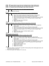
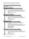
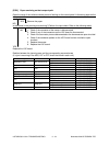
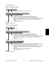
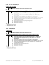
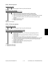
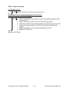
[E550] Paper remaining on the transport path
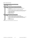
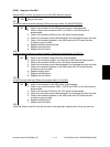
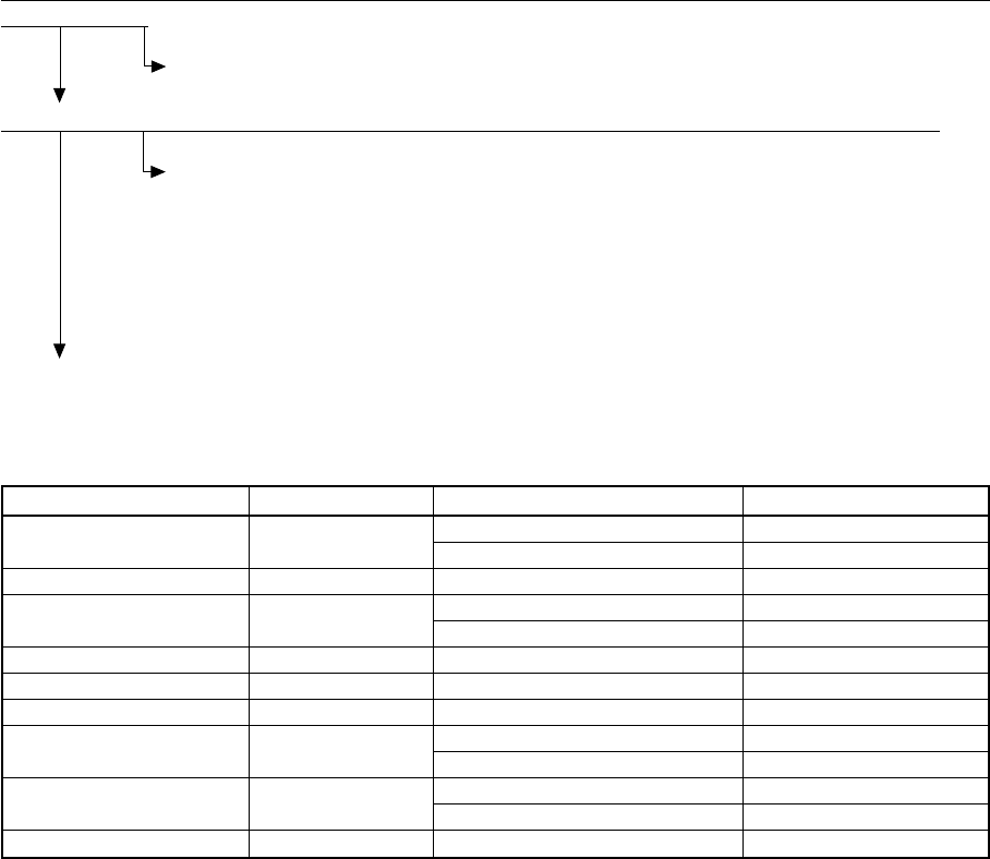
Open the cover of the unit/area whose picture is flashing on the control panel. Is there any paper on the
transport path?
YES Remove the paper.
NO
Is the sensor in the jamming area working? (Perform the input check: Refer to the following table)
NO 1. Check if the connector of the sensor is disconnected.
2. Check if any of the connectors on the LGC board is disconnected.
3. Check if the connector pins are disconnected or the harnesses are open circuited.
4. Check if the conductor pattern on the LGC board is short circuited or open
circuited.
5. Replace the sensor.
6. Replace the LGC board.
YES
Replace the LGC board.
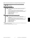
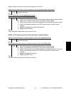
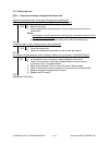
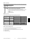
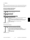
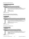
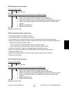
Relation between the jamming area and the corresponding sensors/covers
(If a jam is occurring in the ADU, LCF or PFP, check the board in each unit.)
Jamming area
Registration area
Exit area
ADU
Bypass unit
Feeding area (equipment)
LCF
PFP
Bridge unit
Finisher
Test Mode/Input check
03-[FAX]ON/[9]/[E]
03-[FAX]ON/[3]/[H]
03-[FAX]OFF/[7]/[H]
03-[FAX]OFF/[8]/[H]
03-[FAX]OFF/[8]/[G]
03-[FAX]ON/[9]/[D]
03-[FAX]ON/[3]/[G]
03-[FAX]OFF/[5]/[G]
03-[FAX]OFF/[2]/[D]
03-[FAX]OFF/[4]/[D]
03-[FAX]ON/[0]/[C]
03-[FAX]ON/[0]/[A]
-
Cover
Jam access cover
Fuser cover
ADU
Bypass unit
Side cover
LCF side cover
PFP side cover
Bridge unit
Finisher door
Sensor
Registration sensor
Upper drawer feed sensor
Exit sensor
ADU entrance sensor
ADU exit sensor
Bypass feed sensor
Lower drawer feed sensor
LCF feed sensor
PFP upper drawer feed sensor
PFP lower drawer feed sensor
Bridge unit transport sensor-1
Bridge unit transport sensor-2
Sensors in the finisher


