


IN-1
INDEX
A
Abbreviations ..........................................AP-9
ALARM ACK key................................1-2
, 2-9
Analog output .......................................... 5-10
Analog speed .......................................... 5-10
B
Beam direction ........................................ 5-10
Berthing display
description............................................... 3-1
range ....................................................... 3-2
Berthing line
creating ................................................... 3-8
deleting.................................................. 3-13
sharing .................................................. 3-12
BRILL key
dimmer controller .............................1-3
, 1-5
main display unit ..............................1-2
, 1-5
Brilliance
display ..................................................... 1-5
key (dimmer) ........................................... 5-4
C
Control description
dimmer controller .................................... 1-3
display unit .............................................. 1-1
remote controller ..................................... 1-3
Current averaging ................................... 5-10
Current direction format ............................ 2-5
Current measurement depth ................... 5-10
D
DAY/NT key
dimmer controller .............................1-3
, 1-9
main display unit ..............................1-2
, 1-9
Depth measurement reference ................. 2-5
Dimmer controller...................................... 1-3
Direction symbols
format ...................................................... 5-5
location (nav data and berthing displays) 5-6
speed graphic display ............................. 4-3
DISP key
main display unit ...................... 1-1
, 1-5, 1-7
remote controller ...................... 1-3
, 1-5, 1-7
Display arrangement ................................. 5-1
Display unit controls .................................. 1-1
Display unit test......................................... 6-9
E
Echo monitor ........................................... 6-12
ENT key .............................................1-2
, 1-8
Error message........................................... 6-4
F
Fuse replacment ....................................... 6-2
H
Heading averaging .................................. 5-10
I
Initial settings restore .............................. 6-15
Input sentences.......................................AP-3
Interference rejector ................................ 5-10
K
Key beep ................................................... 5-4
Key dimmer ............................................... 5-4
L
LCD test .................................................. 6-10
Log pulse output...................................... 5-10
Log pulse speed source .......................... 5-10
M
Maintenance.............................................. 6-1
Menu operation ......................................... 1-9
Menu tree ................................................AP-1
MENU/ESC key.................................. 1-2
, 1-7
MODE key (remote controller) ...........1-3
, 1-6
N
Navigation data display
description............................................... 2-1
indications ........................................ 2-1, 2-2
Navigation data ON/OFF........................... 3-7
O
Output sentences ....................................AP-6
P
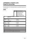
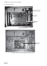
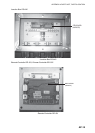
Parts list ................................................AP-12
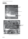
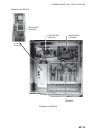
Parts location ........................................AP-13
Past track
description............................................... 3-3
format ...................................................... 3-5
ON/OFF................................................... 3-4
Power on/off .............................................. 1-4
Predicted track
description............................................... 3-4
ON/OFF................................................... 3-4
plot time................................................... 3-5
Product life ................................................ 6-2
PWR key ............................................1-1
, 1-4
R
Range (berthing display) ........................... 3-2
Remote controller...................................... 1-3
RNG key.............................................1-2
, 3-2
ROT sensor............................................... 2-8
S
Ship vector ................................................ 3-6
Ship’s speed averaging........................... 5-10
Speed alarm.............................................. 2-9
Speed graphic display