


APPENDIX
AP-8
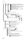
Digital Interface (IEC 61162-1 Edition 4, IEC 61162-2)
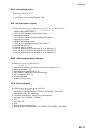
Sentence data
Input sentences
ABM, ACA, ACK, AIR, BBM, DTM, GBS, GGA, GLL, GNS, HDT, LRF, LRI, OSD, PIWWIVD,
PIWWSPW, PIWWSSD, PIWWVSD, RMC, ROT, SSD, THS, VBW, VSD, VTG
Output sentences
ABK, ACA, ACS, ALR, LRF, LR1, LR2, LR3, TXT, PIWWSPR, VDM, VDO
Transmission interval
ABK: With each event
ACA, ACS: At RX
ALR: 30 s during alarm, 1 min normally no alarm
LRF, LR1, LR2, LR3: At RX
TXT: Each update
VDM: At RX
VDO: 1 s
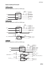
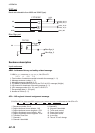
Load requirements as listener
Isolation: Provided
Input Impedance: Input Impedance: 110 ohms (130K ohms without jumper plug)
Max. Voltage: ±14 V to GNDiso
Threshold: ±0.2 V (A-B)
Output drive capability
Differential driver output
R=50 ohm 2 v min.
R=27 ohm 1.5 V min.
Driver short-circuit current
60 mA min. 150 mA max.
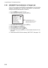
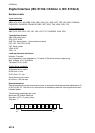
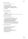
Data transmission
Data is transmitted in serial asynchronous form in accordance with the standard referenced in 2.1
of IEC 61162-1/2. The first bit is a start bit and is followed by data bits, least-significant-bit as il-
lustrated below.
The following parameters are used:
Baud rate: 38.4 Kbps /4800 bps
Data bits: 8 (D7 = 0), parity none
Stop bits: 1
D0 D1 D2 D3 D4 D5 D6 D7
Start
bit
Stop
bit
Data bits