


2. RADAR, CHART RADAR OPERATION
2-39
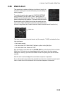
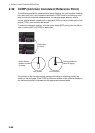
2.28 Interswitch
The interswitch uses a network to transfer multiple radar signals to the monitor units
connected in the network. A master/slave relation can be set for a single radar signal
and that signal can be shown on multiple displays. Up to four antennas and four dis-
play units can be connected. Set the radar display and antenna groups from the [An-
tenna] button on the Status bar.
When you switch to a different antenna, the heading skew and timing adjustment (set
at installation) for that antenna are automatically applied.
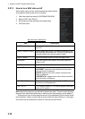
The [Antenna] button on the Status bar shows current antenna selection.
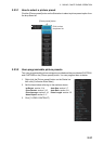
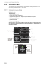
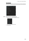
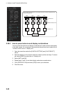
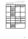
2.28.1 Displaying antenna information
The [ANT SELECT] display shows:
• Radar band, output power and antenna position of each antenna currently powered.
(If an antenna is not powered, its data area is blank.)
• Current antenna and display combinations.
To show antenna information, open the menu then select the [8 INITIAL SETTING]
and [5 ANT SELECT] menus.
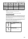
[Antenna] button
- ANT-3(M): Antenna no. 3, (M)=Master (or (S)=Slave)
- X-BAND (or S-BAND)