


2-6
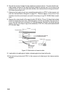
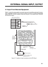
Wiring
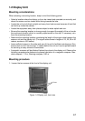
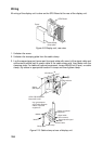
All wiring of the display unit is done on the SPU Board at the rear of the display unit.
Cover
SPU Board
Cable clamp,
clamp plate
Figure 2-9 Display unit, rear view
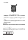
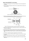
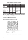
1. Unfasten the cover.
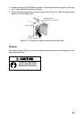
2. Unfasten the clamping plate from the cable clamp.
3. Lay the copper tape part (armor part for signal cable with armor) of the signal cable and
anticorrosive shield part of power cable in the cable clamp and then fasten with the
clamping plate. For cables of optional equipment, loosen M6x35 bolt (2 pcs.) on cable
clamp, lay cables in appropriate location in clamp and then tighten clamp.
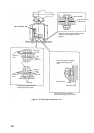
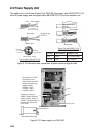
SPU Board
To DJ-1
Ground wire
Cables of optional
equipment
Signal cable
(from scanner)
Power cable
M6X35
M4X15
Clamp plate
Cable clamp
Screw
(M3, 2 pcs.)
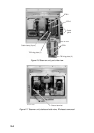
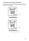
GYRO PROCESSOR
Board 64P1106A
J5
* Lay gyrocompass
signal cable beneath
cables of optional
equipment.*
Gyrocompass signal
cable
Figure 2-10 Cable clamp at rear of display unit