


5-4
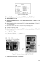
DIP switch, jumper wire settings
Default setting
The default setting of all DIP switches is off and all jumpers wire are set to “#1.” (Note that
jumper wire JP1 is set at #1, #2, and #3.) In those settings the gyrocompass having the
following characteristics can be directly connected; modification of the GYRO CONVERTER
Board is not necessary.
AC synchronous signal: 50/60 Hz
Rotor voltage: 60 V to 135 V AC
Stator voltage: 60 V to 135 V AC
Gear ratio: 360x
Supply voltage: 30 V to 135 V AC
If the specifications of the gyrocompass differ from those mentioned above, change jumper
wire and DIP switches settings on the GYRO CONVERTER Board. Settings may be
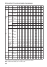
changed according to gyrocompass specifications or make and model of gyrocompass
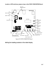
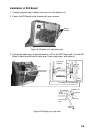
(see page 5-6). For the location of DIP switches and jumper wires, see page 5-7.
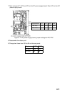
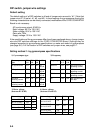
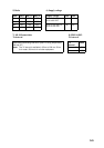
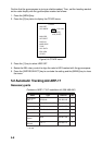
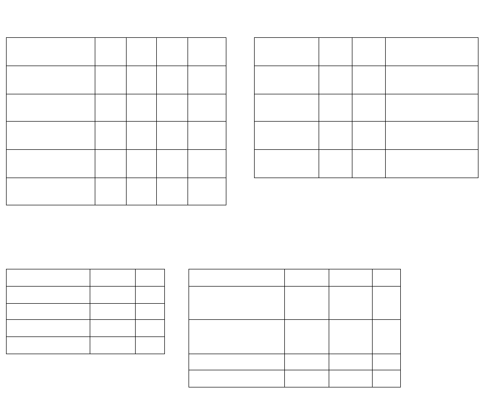
Setting method 1: by gyrocompass specifications
1) Gyrocompass type 2) Frequency
Gyrocompass
t
yp
e
SW
1-4
SW
1-5
SW
1-6
JP1 Frequency SW
1-7
SW
1-8
Remarks
AC synchronous OFF OFF OFF #1,
#2, #3
50/60 Hz OFF OFF AC synchronous
pulsatin
g
current
DC synchronous OFF OFF OFF #2,
#3, #4
400 Hz ON OFF AC synchronous
pulsatin
g
current
DC step ON OFF OFF #4,
#5, #6
500 Hz OFF ON AC synchronous
pulsatin
g
current
Full-wave
pulsatin
g
current
OFF ON OFF #4,
#5, #6
DC ON ON DC synchronous
DC step
Half-wave
pulsatin
g
current
ON ON OFF #4,
#5, #6
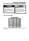
3) Rotor voltage
(between R1 & R2)
4) Stator voltage
(between S1 and S2)
Rotor volta
g
e SW 2-1 JP3 Stator volta
g
e SW 2-2 SW 2-3 JP2
20 V to 45 VAC ON #2 20 V to 45 VAC, or
20 V to 60 VDC
ON OFF #2
30 V to 70 VAC OFF #2
40 V to 90 VAC ON #1 20 V to 45 VAC, or
20 V to 60 VDC
OFF OFF #2
60 V to 135 VAC OFF #1
40 V to 90 VAC ON OFF #1
60 V to 135 VAC OFF OFF #1