


5-13
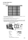
5.3 Video Plotter RP-17
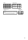
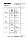
Necessary parts
Video plotter installation kit RP-17-17E-2 (Code No. 000-086-989)
emaNepyTytQ.oNedoC
ksiDyppolFXX12519530.ON1097-294-800
draoB71-PRA9529P301098-294-800
.yssAelbaC3360-081011-005-800
)rettolp(lebaL1048-430-411001-801-001
)drac-M(lebaL6019-431-301032-532-001
wercSdaehnaPW0072C8X3M5404-188-000
launaMs'rotarepOE-71-PR1048-294-800
.yssArotcennoCHX)P5(6971-301038-264-800
eroCladioroT21-51-52-CFT1396-921-000
eiTelbaC051-VC1523-075-000
pmalCH50-KC1742-075-000
)Z(FgnibuTknirhSm1.052.0X31478-501-000
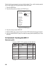
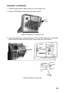
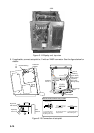
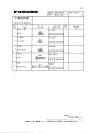
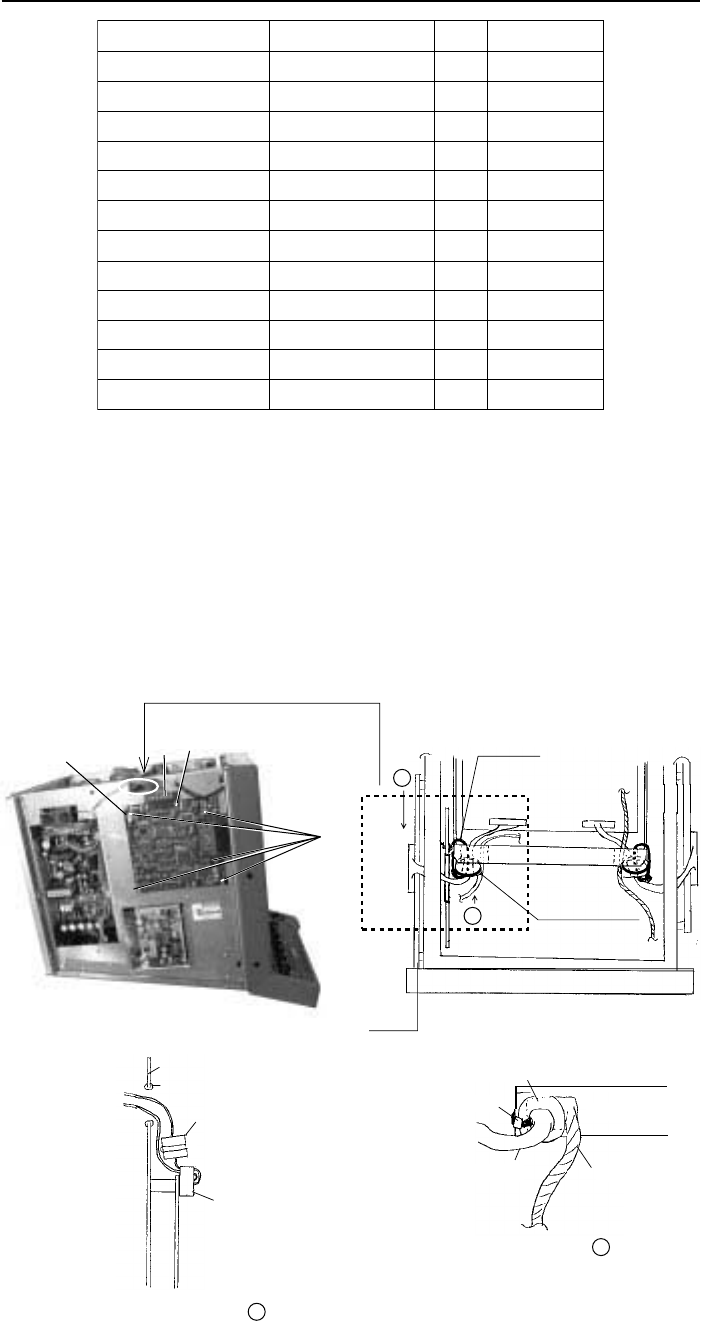
1. Turn off the power and the switch S2 (for AC set) at the rear of the display unit. Turn off
all equipment connected to the radar.
2. Unfasten eight screws to detach the cover from the display unit.
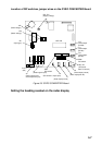
3. Fasten the RP Board to the chassis with five screws.
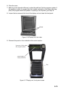
4. Connect the cable assy. (supplied) between J106 on the SPU Board and J4 on the RP
Board. Attach toroidal core to cable assy. Fasten cable assy. with cable tie. See the
drawing below and at the top of the next page for details.
Screw
RP-17 Board 03P9259A
J1
J4
Front Panel
Cable Tie
CV-150
Toroidal Core
TFC-25-15-12
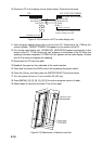
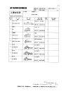
RP-17
Board
SPU Chassis
03P9230
SPU Board
J4
J106
A
B
SPU Chassis
Toroidal Core
Exploded View of
A
Square Bushing
Chassis
J4
RP-17 Board
03P9259A
Toroidal Core
Exploded View of B
Cable Tie
Cable Assy.
Inside View
Pass through
hole.
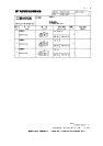
Figure 5-13 Display unit, left side view