


5-3
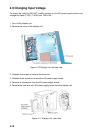
Connection of gyrocompass cable
rotcennoCepyTpetSepyTorhcnyS
4J
1#1S1S
2#2S2S
3#3S3S
4#– –
5#.G.F.G.F
5J
1#– 2R
2#MOC1R
3#.G.F.G.F
6. Attach the instruction label (supplied) on the inside of the rear cover.
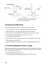
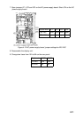
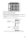
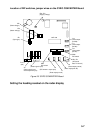
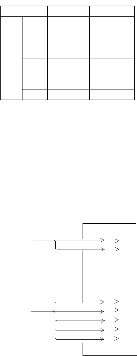
Connection of external power supply
An external power supply is necessary when the repeater signal is step-by-step type and
the step voltage is below 20V or output voltage is less than 5 W.
1. Cut jumper wire JP1 on the GYRO CONVERTER Board when an external power sup-
ply is used.
2. Connect gyro cable and power cable as shown below.
GYRO CONVERTER Board
[A] 64P1106
1 R2
Either connection
in case of DC
polarity.
J5
2 R1/COM
External Power Supply
20 - 135 VAC
20 - 100 VDC
1 S1
2 S2
3 S3
4 T
5 F.G.
Gyrocompass
(Step type)
S1
S2
S3
COM
F.G.
J4
Figure 5-2 Connection of external power supply to GYRO CONVERTER Board