


5-2
Installation and wiring
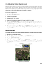
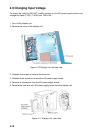
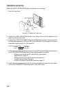
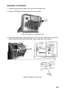
Install the GYRO CONVERTER Board in the display unit as follows:
1. Open the rear cover.
64P1106A Board
J7
J1
Screw
(M3 x 8)
Fuse
Spacer
Figure 5-1 Display unit, rear view
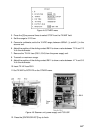
2. Fasten the GYRO CONVERTER Board to the display unit so that the battery on the
board is at the top left corner.
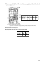
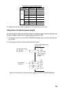
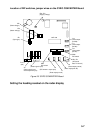
3. Connect the GYRO CONVERTER Board to the SPU Board as below. Use the connec-
tor assemblies attached to J206 and J207 on the SPU Board. Do not use the connector
assemblies supplied with Gyro Converter kit.
GYRO CONVERTER Board SPU Board
J1 (14P) J207 (6P)
J7 (5P) J206 (5P)
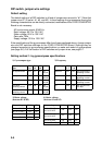
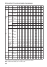
4. Confirm gyrocompass specifications and set up the DIP switches and jumper wires on
the GYRO CONVERTER Board according to gyrocompass connected:
• Setting jumper wires and DIP switches by gyrocompass
specifications: page 5-4
• Setting jumper wires and DIP switches by make and
model of gyrocompass: page 5-6
• Location of jumper wires and DIP switches: page 5-7
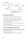
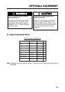
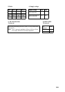
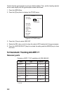
5. Solder the gyrocompass cable to the VH connector assemblies (supplied) and connect
to the GYRO CONVERTER Board as shown in the table below.