


Specifications
A
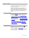
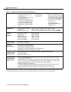
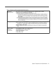
Table 1-1 Technical and Environmental Specifications
Capacities
System
206
Module
Extension Jack
●
●
●
●
●
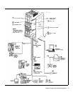
8 outside lines via line jacks on
● 2 outside lines
●
four 206 modules
● 6 extensions
24 extensions via extension jacks
on four 206 modules
1 loudspeaker paging system via
●
PAGE jack on processor module
1 audio source via MUSIC ON
HOLD jack on processor module
2 doorphones, using 2 extension
jacks
Maximum 2 devices per exten-
sion jack, total REN on jack not
to exceed 2* (2 devices require
AT&T 267F2 bridging adapter)
No more than one PARTNER
phone per jack.
A PARTNER display
phone must be connected
to Extension 10.
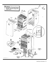
Dimensions
●
Processor/206 modules
11“(D) x 17"(H) x 1.5”(W)
or 4.3cm x 6.6cm x .58cm
● Control unit
12”(D) x 19"(H) x 11“(W)
or
4.7cm x 6.8cm x 4.3cm (assembled)
● PARTNER telephones
9.5”(D) x 5"(H) x 6.75”(W) or 3.7cm x 1.9cm x 2.6cm (assembled)
Weights
● Processor module
4.0 lbs or 8.8 kgs
(approx.)
● 206 module
4.5 Ibs or 9.9 kgs
● Backplane & cover
5.5 Ibs or 12.2 kgs
● MLS-6 telephone
1.8 lbs or 4.0 kgs
● MLS-12 telephone
2.0 Ibs or 4.4 kgs
● MLS-12D telephone
2.1 Ibs or 4.6 kgs
Switch Fabric
● Full digital, nonblocking
Electrical
● 2 amps at full system capacity
Specifications
● 200 watts at full system capacity
● 4-day memory backup (96 hours)
● Dissipation of power (65 watts during normal operation)
●
684 BTUs/hour at peak; 225 BTUs/hr at normal
Extension Jack
● Ringing voltage: +5VDC, -140 VDC peak to peak; Trapezoidal wave shaping
Specifications
● 48-volt talk battery
● Ringing frequency: 20 Hz
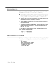
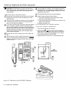
Environmental
●
Mount on a wall or sturdy, level surface at least 2 feet (.6 meters) from the floor (wall mount-
Requirements—
ing strongly recommended)
Control Unit
● Locate within 5 feet (1.5 meters) of an electrical outlet not controlled by a switch and within
5 feet (1.5 meters) of the network interface jacks, when using supplied 7
-
(2.1-meter) cords
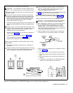
● Operating temperature 32° to +I04°F (0° to +40
o
C), not in direct sunlight
● Humidity 15%-90%, noncondensing
● For proper ventilation and easy replacement of modules, provide at least 6“ (2.34cm) clear-
ance at the top and sides and 1 foot (0.3 meters) at the front of the control unit.
●
Locate in an area
free of excess moisture, corrosive gases, dust, and chemicals
*The two devices combined on an extension jack can be a PARTNER phone with a standard device, or two standard devices; DO NOT connect
two PARTNER phones to the same extension jack. If a device lists two RENs, use the higher number when adding up RENs.
1-4 System Components and Specifications