


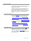

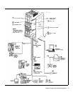

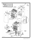

An Example System Setup
This PARTNER Plus System has 4 outside lines and 8 extensions connected to a variety of PARTNER phones and other equipment.
The boldface numbers refer to the following list which gives a brief description of the system’s hardware components.
Control Unit.
The heart of the PARTNER Plus system, the
control unit consists of a backplane, cover (not shown), one
processor module, plus up to four 206 modules. The
backplane channels power to the system and connects the
incoming telephone lines to the system.
Processor Module.
The processor module contains the
electronics that provide most of the system features. It also
has audio and paging jacks.
Page Jack.
The loudspeaker paging system plugs
directly to this modular jack.
Music-On-Hold Jack.
The audio source plugs directly
into this RCA jack.
206 Module.
Each 206 module has jacks for 2 incoming
telephone lines and 6 extensions.
The system can have up
to four 206 modules.
Line Jacks.
Outside telephone lines connect to the top 2
jacks on each 206 module.
Extension Jacks.
Telephones and other telecommunica-
tions equipment connect to the bottom 6 jacks on the 206
modules.
AC Power.
An ordinary 110 VAC grounded wall outlet (not
controlled by an on/off switch) supplies power to the control unit.
Network Interface Jacks.
Incoming telephone lines
service the system through these jacks. These lines can be
from the local telephone company or another system, such
as a PBX (Private Branch Exchange) or Centrex.
PARTNER Display Phone: Extension 10.
The
system operator in this example is the receptionist on
extension 10 and has a PARTNER display phone. This
phone can handle 8 outside lines and has a display showing
the time, number dialed, duration of call, and programming
messages. Also, its programmable buttons (two with lights)
can be programmed to store additional features and Auto
Dial numbers. Because the display is required for system
programming, extension 10 on your system must also have
an PARTNER display phone.
Standard Touch-Tone Telephone Used as a
Power FailureTeIephone.
In a power failure, the first
extension jack on each 206 module connects to the first
outside line on that module to provide continuous service to
standard non-PARTNER telephones. In this example
system, the PARTNER phone on extension 10 will not work
during a power failure. However, the receptionist can use
the standard touch-tone phone connected to extension 10 to
place and receive calls on line 1.
AT&T 267F2 Bridging Adapter.
This adapter com-
bines the standard touch-tone phone and the PARTNER
display phone on one extension jack. The adapter has two
modular jacks, one for each phone. You can use the
bridging adapter to combine any two devices (PARTNER
telephones, industry-standard telephones, or other equip-
ment) on one extension jack as long as the total Ringer
Equivalence Number on each extension jack is 2 or less. (A
device’s Ringer Equivalence Number—REN--is shown on its
UL label.) The bridging adapter plugs into a wall jack or
directly into an extension jack on the 206 module.
PARTNER 12-Button Phone.
This phone is Iike the
PARTNER display phone, but it has no display.
PARTNER 6-Button Phone and Answering
Machine.
Using a 267F2 bridging adapter, both a
PARTNER 6-button phone and an answering machine are
connected to one extension. The PARTNER 6-button phone
accommodates up to 4 outside lines.
Industry-Standard Telephone.
A standard single-line
touch-tone phone (such as you might have in your home) is
connected directly to the extension jack.
Doorphone.
A doorphone is installed at the entrance.
When someone at the entrance presses the button on the
doorphone, up to 5 designated telephones in the office ring
automatically.
Bell.
A loud bell connected directly to the extension jack
rings when the extension is called.
Fax Machine and Standard Telephone.
A
fax
machine and standard touch-tone phone are connected
together on an extension jack. This setup lets you share the
fax line with a telephone. If you pick up the phone and hear a
fax signal, you can simply hang up to let the fax machine
receive the call.
Alternatively, you can use a PARTNER phone at another
extension to monitor the fax machine (“Fax Management”).
To do so, first use System Programming to identify the fax
machine extension. Then program a lighted button on a
PARTNER phone with the fax extension number as an Auto
Dial number. You can then use the Auto Dial number to
quickly transfer calls from that extension to the fax machine.
In addition, the light on that button shows whether the fax
machine is in use, busy, returning a call you transferred to it,
or not answering calls. If your AT&T fax machine includes
the “Notify” feature, the fax machine can also notify you
when a fax has been received.
Modem.
A modem connected directly to an extension jack
provides data communications capability to the personal
computer.
Loudspeaker Paging System.
A paging system is
connected to the modular PAGE jack on the processor
module. The PARTNER Plus system is compatible with
AT&T’s paging systems.
Music-On-Hold Source.
AT&T’s MAGIC-ON-HOLD
®
cassette deck is connected to the RCA jack on the proces-
sor module to provide customized music and messages for
callers on hold. For information on MAGIC-ON-HOLD, call
your AT&T representative or the AT&T Sourcebook at
1 800 451-2100. You can connect any type of audio
equipment to your system (including a CD player, casette
player, stereo receiver, etc.), but you must supply an audio
cord with an RCA plug.
NOTE:
Users of equipment that rebroadcasts copyrighted
music or other material may be required to obtain a license
from a third party such as ASCAP or BMI.
Figure 1-1 Example System Setup
1-2 System Components and Specifications