


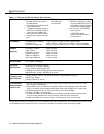


General Guidelines
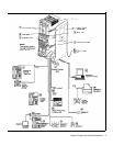
Instructions for installing the control unit, telephones, and other equipment are
on the following pages (figures 2-1 to 2-3). Before you begin, please note the
following guidelines:
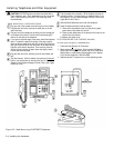
If you combine a standard phone
and PARTNER phone on one
extension, you may want to turn
off the ringer of the standard
phone during normal use.
Using the System Planner is essential for knowing where phones and other
equipment are to be installed, and how the system and phones are to be
programmed.
Install the control unit so that it meets the environmental and electrical
requirements listed on p. 1-4.
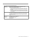
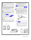
If wall mounting the control unit, you will need four #12 screws appropriate
for the type of wall and weight of the control unit.
When connecting wires to the jacks on a 206 module, leave at least 2 feet of
slack for removing the module without first disconnecting the wires. If you
later replace the module, you can remove the old module with the wires in
place and plug them into the new module one at a time.
PARTNER phones require at least 2-pair wiring and are compatible with
AT&T 4-pair PDS wiring.
Standard phones and other equipment require 1-pair mounting cords (AT&T
D2R mounting cords recommended).
When connecting two devices to a single extension, use only an AT&T 267F2
bridging adapter.
Connect a PARTNER display phone to extension 10 for system
programming.
Do not connect doorphones to extensions 10, 16, 22, or 28.
Do not install telephones out of the building.
A hotline phone must be a standard, single-line phone, not a PARTNER
telephone. However, the hotline phone can ring any type of phone.
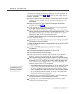
During a power outage, neither the system’s features nor PARTNER phones
work. However, standard, single-line touch-tone or rotary phones connected
to extensions 10, 16, 22, and/or 28 can be used to place and receive calls.
These extensions connect directly to lines 1, 3, 5, and 7, respectively. To
prepare for a power failure, AT&T recommends:
■
Store standard phones close to extensions 10, 16, 22, and/or 28. During
a power failure, replace the PARTNER phone with the standard phone.
Or, connect a standard phone to these extensions at all times, either by
itself or combined with an PARTNER phone via a 267F2 bridging adapter.
■
Do not program a Hotline on extension 10, 16, 22, or 28 to keep these
extensions available for power failure use.
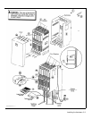
If upgrading from a one-module PARTNER system, remove the rubber feet
that may be attached to the 206 module before installing.
If upgrading from a two-module PARTNER system, remove the module
connector from the the two modules.
Installing the Hardware 2-1