


Installing the Control Unit
CAUTION:
To prevent electrostatic discharge, overheat-
ing, or other damage, environmental and electrical condi-
tions must meet the specifications on p. 1-4.
MOUNT THE BACKPLANE ON A WALL
Hold the backplane in place on the wall. Using the four
screw keyholes in the backplane as a template, mark the
screw locations on the wall.
Start the four #12 screws, Ieaving thereabout 1/4” out from
the wall. Use screws appropriate for the wall surface-
when loaded with five modules, the control unit weighs
37.5 pounds.
Slip the backplane onto the screws and tighten them.
INSERT THE MODULES
CAUTION:
Do not connect AC power cord before inserting
modules.
Slide the first 206 module straight into the left most slot of the
backplane. Push slowly but firmly until the module snaps
into place (you should hear and feel two snaps). The
module must be securely attached to the rear of the
backplane and held into place by the locking tab on the
bottom front of the backplane/module slot. Insert the next
206 module in the second slot from the left. Note the align-
ment of dovetails between each module when modules are
installed next to each other.
CAUTION: Do not force the module. If it does not insert
easily, pull down on the front locking tab, remove the
module, clear any obstruction, and insert the module again.
Insert the processor module in the center slot. Insert the
other 206 modules from left to right, without skipping slots.
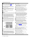
Label
the line
and extension
jacks as shown below:
CONNECT THE OUTSIDE TELEPHONE LINE CORDS
Test for dial tone at the network interface jacks before connecting outside
lines.
Connect the outside telephone line cords to the line jacks on
the 206 modules, starting with the top line jack on the
leftmost 206 module. Route the cords alongside the tele-
phone cords. Leave at least 2 feet of slack in the cords so
that you can easily reconnect the cords during replacement.
Connect the free end of each line cord to the appropriate
network interface jacks.
TEST THE SYSTEM
Connect the AC power cord to the power jack on the top right
rear of the backplane. Press firmly until it locks into place.
Make sure the circuit breakers on each module and the
backplane are pushed in.
Plug the other end of the power cord into a grounded 3-
prong wall outlet not controlled by a switch.
Check all green lights on the front of the unit. If any lights are
out, remove the power cord and reseat the module.
To test the lines, plug a PARTNER 12-button phone into
extension 10. Press the line button for each outside line and
listen for dial tone. Repeat for extensions 16, 22, and 28.
Disconnect the power cord before continuing.
CONNECT THE MODULAR TELEPHONE CORDS
Connect the modular telephone cords from the telephones to
the extension jacks on the 206 modules, starting with the top
extension jack on the leftmost 206 module. Route the cords
through the hook on the front of the module, then through the
slot between the module and the base of the backplane.
Leave at least 2 feet of slack in the cords so that you can
easily reconnect the cords during replacement.
CONNECT THE MUSIC-ON-HOLD SOURCE (OPTIONAL)
Follow these steps to connect the audio source to the control unit.
(Assemble and use according to the manufacturer’s directions.)
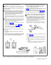
Using a flathead screwdriver, turn the volume control on the
processor counterclockwise to the lowest setting.
Insert the RCA plug into the RCA jack on the processor
(labeled MUSIC ON HOLD). Route the cord through the
hook on the front of the module and the slot between the
module and the base of the backplane.
Connect the cord to the music-on-hold source according to
the manufacturer’s directions. Finally, adjust the volume
using the volume control on the processor. Place a call on
hold and listen to the level while adjusting. If you do not hear
music at any volume setting, check system programming
procedure #602
(chapter 3).
CONNECT THE LOUDSPEAKER PAGING SYSTEM
(OPTIONAL)
Only the steps for connection to the control unit are included here. Follow
the rnanufacturer's directions for setting up and using it.
Insert the modular plug for the paging system into the
modular jack labeled PAGE on the processor. Route the
cord as described in step 16.
Connect the cord to the loudspeaker paging system accord-
ing to the manufacturer’s directions.
CONNECT THE AC POWER CORD
Connect the power cord as described in steps 9, 10, and 11.
INSTALL THE OUTSIDE COVER
Holding the sides of the cover, slide the cover onto the front
of the modules until it meets the backplane.
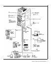
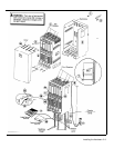
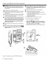
Figure 2-1 Control Unit Installation
2-2 Installing the Hardware