


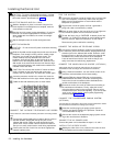
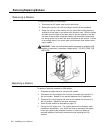

WALL MOUNTING A PARTNER TELEPHONE
WARNING:
Do not attempt to unscrew the base from the
phone. To do so will expose you to a risk of electrical shock.
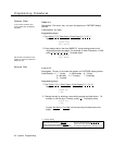
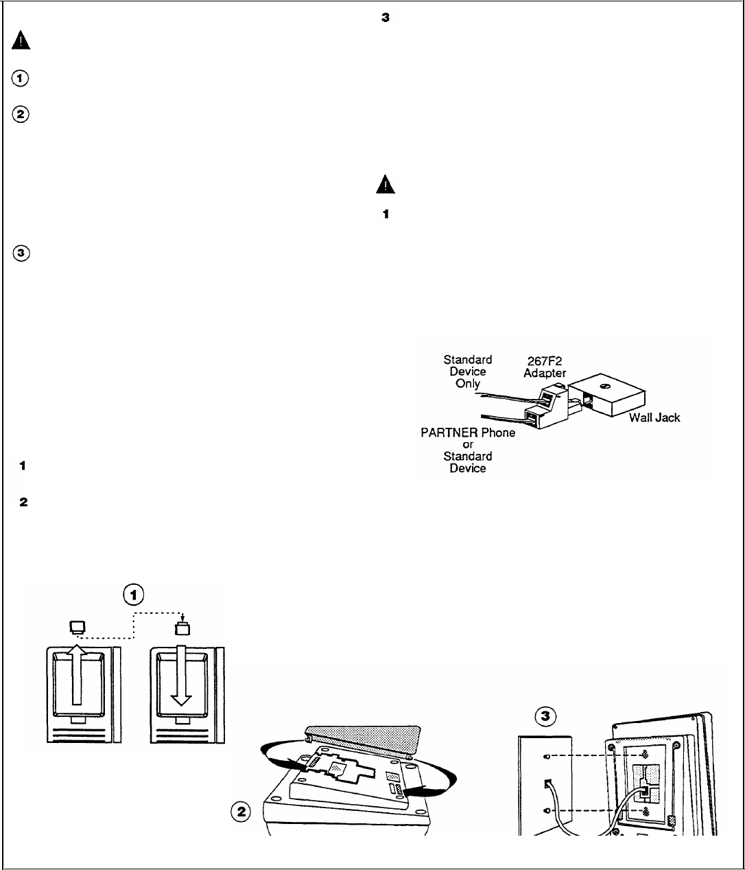
Reverse the plastic hook that sits in the earpiece part of the
handset cradle.
To attach the stand to the base of the phone, gently place
the phone upside down with the low end of the phone to the
tight. Insert the tab on the narrow end of the stand into the
left slot on the base of the phone.
Then
insert the other tab
into the right slot, pushing the stand down and slightly
inward until the tab locks into place.
Attaching the stand is a required step. Do not attempt to wall
mount a corded PARTNER phone without first attaching the
stand.
Finally, plug one end of the handset cord into the jack on the
handset. Plug the other end into the small jack on the side of
the base. If you need a shorter cord, use AT&T’s 2-foot
D4BU-29 mounting cord (not provided).
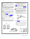
Test the inside and outside line connections as described in
steps 5 and 6 of figure 2-2.
Label the phone as described in step 8 of figure 2-2.
Test the telephone as described in figure 2-2.
Place the Quick Reference card near the telephone.
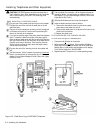
lNSTALLING STANDARD TELEPHONES AND OTHER
EQUIPMENT
Assemble the equipment according to the manufacturer’s
instructions.
Plug the mounting cord into the modular wall jack. If the plug
is loose in the jack, use an AT&T D2R mounting cord. To
order, see appendix
B in the
System Manager’s Guide.
Test a telephone by lifting the handset. You should hear a
dial tone, indicating a good connection on the line. If you
don’t, see chapter 8, in the System Manager’s Guide,
(“Phone Has
Lights but No Dial
Tone”).
If you install a fax machine and want to assign a Fax Management button,
see p. 3-29 to program the extension as a fax extension.
If you install a doorphone, program the system to recognize the Door-
phone and Doorphone Alert extensions. Seepages 3-32 and 3-33.
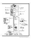
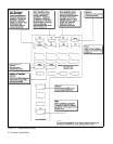
INSTALLING TWO DEVICES ON ONE
EXTENSION
2
3
4
CAUTION:
To
avoid malfunction, follow these installation
instructions, not the ones provided with the equipment.
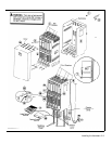
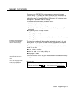
After assembling the equipment, plug the mounting cord of
the non-PARTNER device into the top jack of the 267F2
bridging adapter. Plug the PARTNER phone or second
standard device into the bottom jack (the one with four
wires). If the standard device’s mounting cord is loose, use
an AT&T D2R mounting cord instead.
Plug the adapter into the modular wall jack or directly into
the extension jack of a
206
module. Below is an example:
Test the intercom and outside lines as described in steps 5
and 6 of figure 2-2.
If installing two phones on one extension, test connection:
1 Pickup the handset of the first phone and listen for dial
tone.
2 Pickup the handset of the second phone and listen for
dial tone.
3
If no
dial
tone, see chapter 8, in the System Manager’s
Guide, (“Phone Has Lights but No Dial Tone”).
Figure 2-3 Wall Mounting a PARTNER Telephone and Installing Other Equipment
Installing the Hardware 2-5