


2. WIRING
2-2
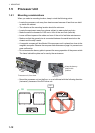
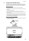
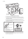
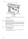
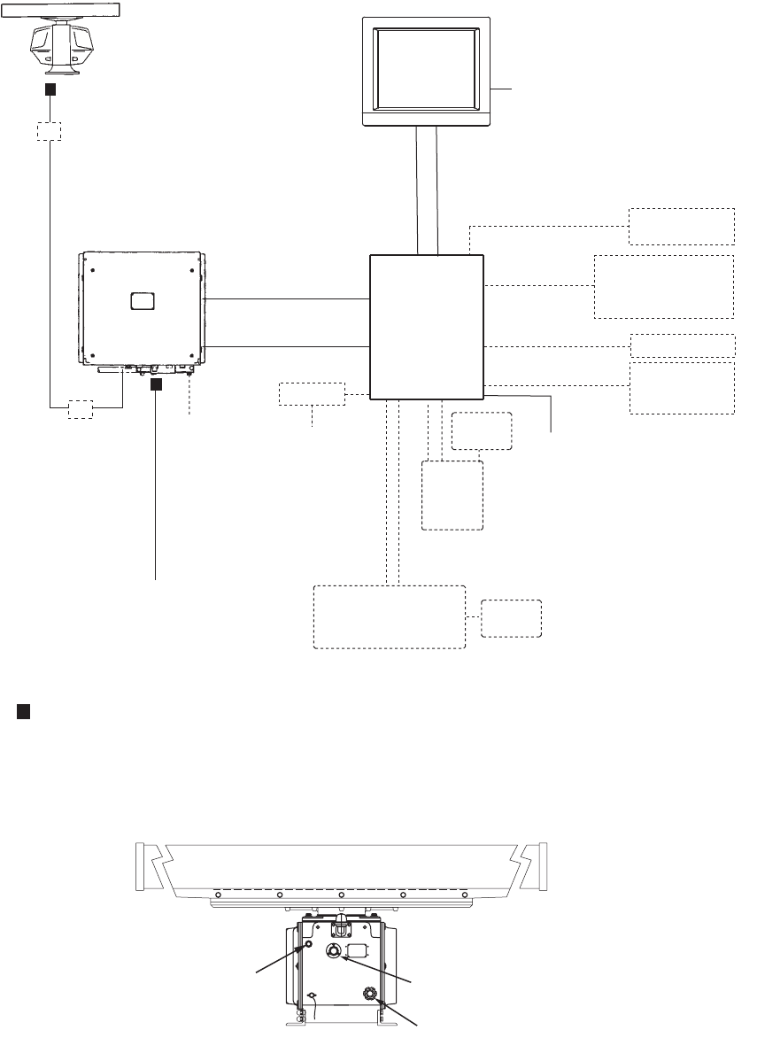
2.2 Antenna Unit
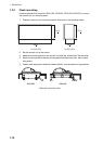
Antenna unit, bow view
1. Open the right side cover on the antenna unit with the hex wrench.
2. Unfasten the cable gland for the signal cable and remove the gasket, flat washers
and blind lid.
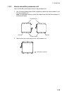
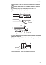
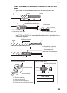
3. Fabricate the signal cable RW-9600 as follows.
a) Remove the outer sheath, armor and inner sheath as shown on the next page.
b) Unravel the shield to expose the wires in the inner layer.
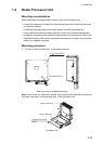
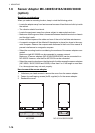
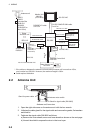
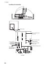
Radar
Processor unit
100-115 VAC/220-230 VAC
Antenna unit
TB801
TB802
RW-9600
15/30/40/50 m
(Max.100 m)
DPYC-2.5
Junction Box
RJB-001*
Junction Box
RJB-001*
: Cable requires fabrication
*: If the cable run between the antenna unit and radar processor unit is more than 100m,
use Junction box RJB-001. However, the maximum length is 300m.
DSUB9P-X2 cable
5 m/10 m
Processor Unit
EC-3000
MPYC-7
or TTYC-1T
Radar Control Unit
RCU-025
Trackball Control Unit
RCU-026
100-230 VAC
100-230 VAC
DVI-D/D SINGLE LINK cable
5 m/10 m
Monitor Unit
MU-231
(FCR-28x9)
USB
memory
MOD-Z702 cable
GYRO
(SYNCHRO,
STEPPER, or
IEC61162-2)
RPU-013
HUB-3000
Sensor Adapter
or HUB-100
XH10P-XH2P cable
(2 m)
FR-FTPC-CY cable
100-230 VAC
GYRO, AIS
TTYCS-4
x2
GPS, LOG, E/S,
WIND, ALRM,
NAVTEX etc.
TTYCS-1Q
x6
5 m
(for USB)
30 m
USB
memory
x2
TTYC-10 cable
System fail, Power fail,
Normal close 1/2.
Normal open 1/2,
ACK IN
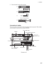
G1_1/4-A
G1-A
G3/4-C
Antenna motor switch
Gland for signal cable (RW-9600)
Gland for power cable
G1_1/4-A