


2. WIRING
2-46
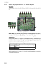
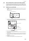
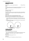
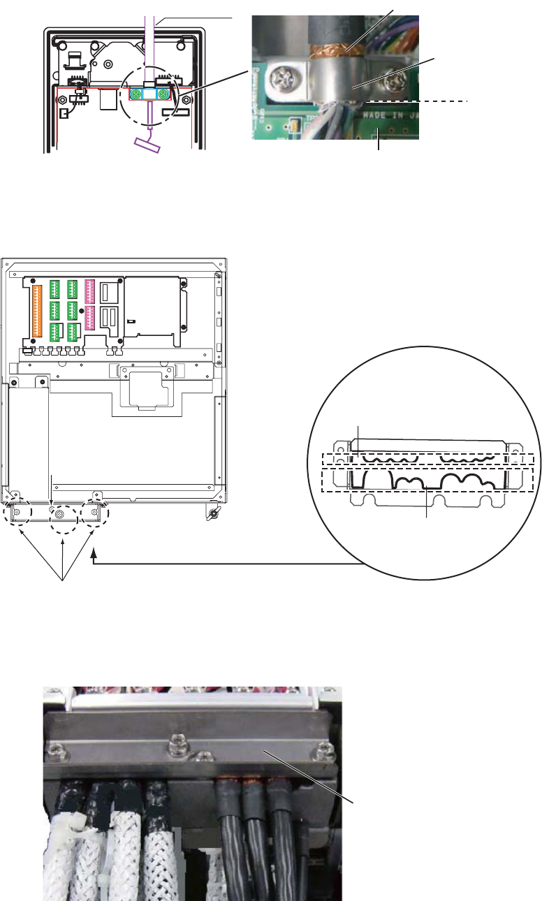
5. Fasten the shield part of the cable assy with the cable clamp (removed at step 2),
then connect the connector at the end of the cable assy to the J1 on the control
unit board.
Note: When clamping, the shield part of the cable must not touch the circuit board.
6. Reattach the control unit cover.
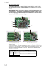
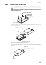
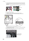
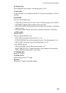
7. Unfasten four screws (M4x8) to remove the processor unit cover.
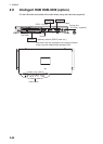
8. Unfasten three bolts to remove the cable clamp (upper) as shown below.
9. Disconnect the control unit cable from the processor unit, then connect the cable
assy (6TPSH-XH12X2-LxxSP2).
10. Set the shields of cables under the cable clamp then tighten the cable clamp.
11. Remount the processor unit cover.
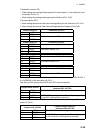
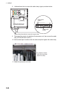
Cable assy
Shield part
Cable clamp
Board
Loosen these three bolts to remove the upper plate.
Loosen this bolt to use
the lower clamp holes.
Loosen this bolt to use
the lower clamp holes.
Clamp holes
(upper)
Clamp holes
(lower)
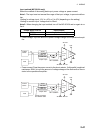
J4
J4
J3
J3
J8
J8
J9
J9
J10
J10
J5
J5
J6
J6
J7
J7
J11
J11
J12
J12
J13
J13
J14
J14
Lay shields of cables
under this clamp then
tighten the clamp.