


4. INSTALLING OPTIONAL EQUIPMENT (for RADAR)
4-3
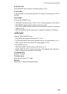
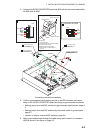
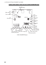
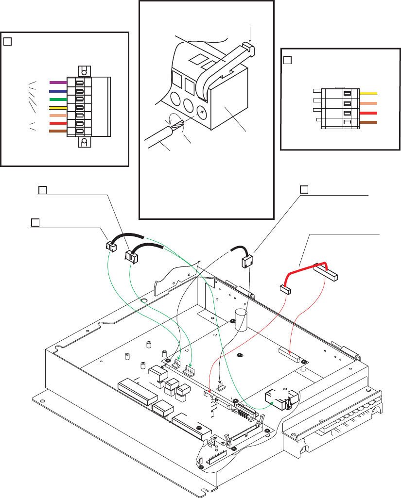
4. Connect the GYRO CONVERTER board and J602 with two connector assemblies
03-2089 and 03-2090.
Connecting connector assemblies
5. Confirm gyrocompass specifications and set up the DIP switches and jumper
wires on the GYRO CONVERTER board according to gyrocompass connected:
• Setting jumper wires and DIP switches by gyrocompass specifications: page 4-
5
• Setting jumper wires and DIP switches by make and model of gyrocompass:
page 4-7
• Location of jumper wires and DIP switches: page 4-8
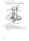
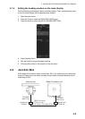
6. Pass gyrocompass cable through the cable clamp and connect it to connector
J602 as shown in the figure on page 4-3.
1
1
4
1
12
1
3
1
2
1
3
1
12
1
5
1
7
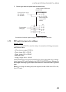
XH-PH connector assy.
03-2088 (6-14P)
NH connector assy.
03-2091 (5P)
VH connector assy.
03-2089 (5P)
VH connector assy.
03-2090 (3P)
J1
P1
J603
P603
GYRO CONVERTER
64P1106A
TB
03P9342
P608
J7
J4
J5
P5
P4
P7
J602
To P608
To J602
1
2
2
P608
1
2
34
BRN
RED
ORG
YEL
1
Connection for P608
2
Connection for J602
17 23456
BRN
RED
ORG
YEL
GRN
BLU
PPL
J602
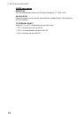
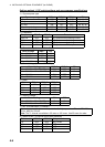
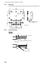
Procedures
1. Twist the cores
2. Press the terminal opener downward.
3. Insert the wire to hole.
4. Remove the terminal opener.
5. Pull the wire to confirm that it is
secure.
Terminal opener
Wiring for WAGO connector
WAGO connector
Wire
Twist
Press downward.
From J5
From J4