


2. WIRING
2-26
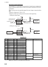
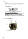
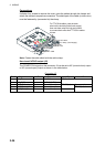
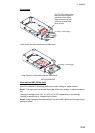
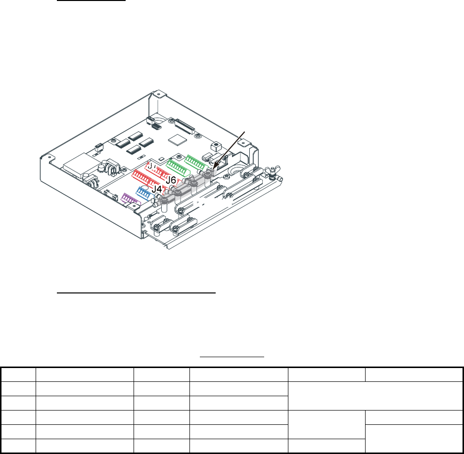
Connections
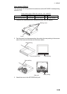
Unfasten four screws to remove the cover, pass the cables through the clamps and
attach the cables to respective connectors. The shield part of the cable (or drain wire)
must be fastened by (connected to) the clamp.
Note: Fasten the cable shield with the cable clamp.
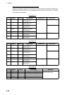
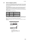
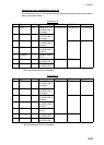
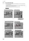
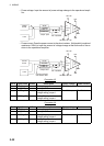
How to set NC/NO output (J2)
The POWER FAIL signal on the connector J2 can be set to NC (normal close) output
or NO (normal open) output as shown in the table below.
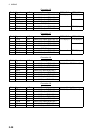
Connector J2
Pin # Signal name In/Out Remarks NO NC
1 24V_IN - 24 VDC DPYC-1.5
2 24V_GND - GND (24 VDC)
3 PWR_FAIL_A Out Power fail output TTYCS(LA)-1 No connection
4 PWR_FAIL_COM Out Power fail output TTYCS(LA)-1
5 PWR_FAIL_B Out Power fail output No connection
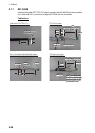
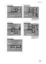
J1
J1
J2
J2
J4
J5
J5
J7
J7
J6
J8
J8
J9
J9
For TTYCSLA cables, pass the drain
wire into the shrinking tube (local supply),
then use these crimp-on lugs and screws
to connect drain wires from TTYCSLA cables
to here.
DPYC1.5
DPYC1.5
MC1.5-W-L cable
MC1.5-W-L cable
TTYCSLA-4
TTYCS-4/
TTYCSLA-4
TTYCS-1Q/
TTYCSLA-1Q
TTYCS-1Q/
TTYCSLA-1Q
FR-FTPC-CY cable
FR-FTPC-CY cable
IV-1.25sq. (Local supply)
IV-1.25sq. (Local supply)