


2. WIRING
2-6
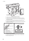
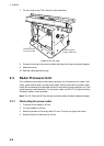
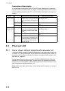
7. Fix the crimp-on-lug FV2-4 (blue) to each conductor.
Antenna unit, left view
8. Connect crimp-lug to the terminal block referring to the interconnection diagram.
9. Attach the cover.
10. Seal the cable gland with putty.
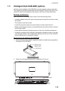
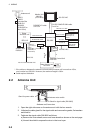
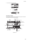
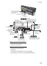
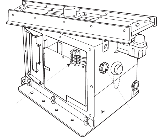
2.3 Radar Processor Unit
Four cables are terminated at the radar processor unit: the antenna unit cable, LAN
cable, power switch cable, and the power cable. Cables other than the power cable
come with a connector pre-attached to them for connection to the processor unit. Fab-
ricate the power cable as below. For the power cable, use DPYC-2.5 (Japan Industry
Standard) cable or the equivalent.
Note: For AC: Pass the AC line through a double-contact breaker (shipyard supply)
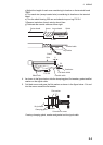
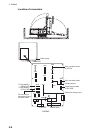
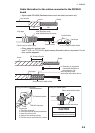
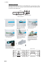
2.3.1 Fabricating the power cable
1. Cut armor of the cable by 40 mm.
2. Cut vinyl sheath by 35 mm.
3. Remove insulation of wires by about 10 mm. Fix crimp-on lugs to the cores.
4. Scrape off paint of the armor by 40 mm.
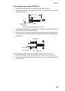
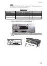
Terminal board
for power cable
Pass the power
supply cable here.