


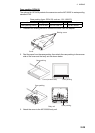
2. WIRING
2-33
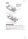
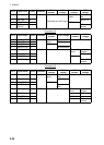
Connector J5
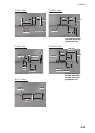
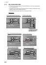
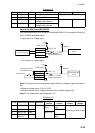
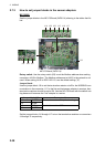
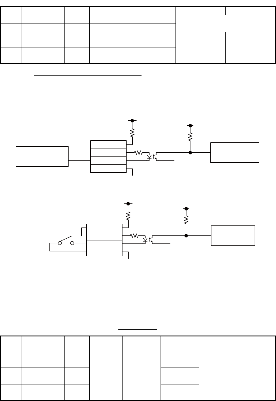
How to set ACK input (MC-3020D)
Use the connectors J3 to J6 on the MC-DIN Board (24P0116) to set the ACK input for
ACK1 to ACK8 as shown below.
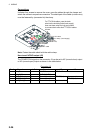
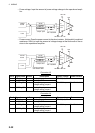
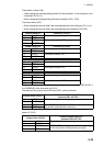
• Input circuit for voltage input
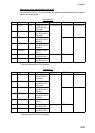
• Input circuit for contact input
Note 1: The input must not exceed the range of the input voltage, to prevent malfunc-
tion.
-Setting for voltage input: 21.6V to 31.2V
-Setting for contact input: Voltage cannot be input (contact signal only).
Note 2: For analog input, see paragraph 2.7.2
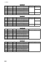
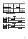
Connector J3
Pin # Signal name In/Out Description Power voltage Power current
1 AN3_IN In Analog 3 input TTYCS(LA)-1
2 AN3_GND - Analog 3 GND
3 CURR3_JP1 - Analog 3 input, power current/
voltage setting jumper 1
Pin #3-#4: open Pin #3-#4: short
4 CURR3_JP2 - Analog 3 input, power current/
voltage setting jumper 1
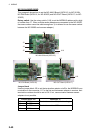
Pin # Signal name In/Out Remarks
ACK1
contact
ACK
voltage
ACK2
contact
ACK2
voltage
1 DC12V_OUT Out ACK1 In Pin #1-#2:
short
No connec-
tion
Depending on ACK1 input
2 DIGI_IN1 In MPYC-12
3 DIGI_RTN1 Out MPYC-12
4 GND
(DC12V)
In No connec-
tion
DC12V_OUT
DIGI_IN1
DIGI_RTN1
GND(DC12V)
GND
5V
DC voltage input
(21.6V to 31.2V)
+
-
12V
GND
to Processor unit
circuit
470Ω/ 0.5W
2.2kΩ / 1W
Register
Photocoupler circuit
GND
5V
12V
GND
470Ω/ 0.5W
2.2kΩ / 1W
Contact input
DC12V_OUT
DIGI_IN1
DIGI_RTN1
GND(DC12V)
Register
Photocoupler circuit
to Processor unit
circuit
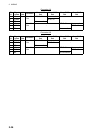
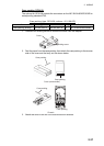
Use NH connector
and AWG24 wire.