


2. WIRING
2-16
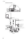
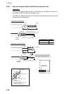
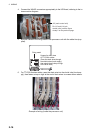
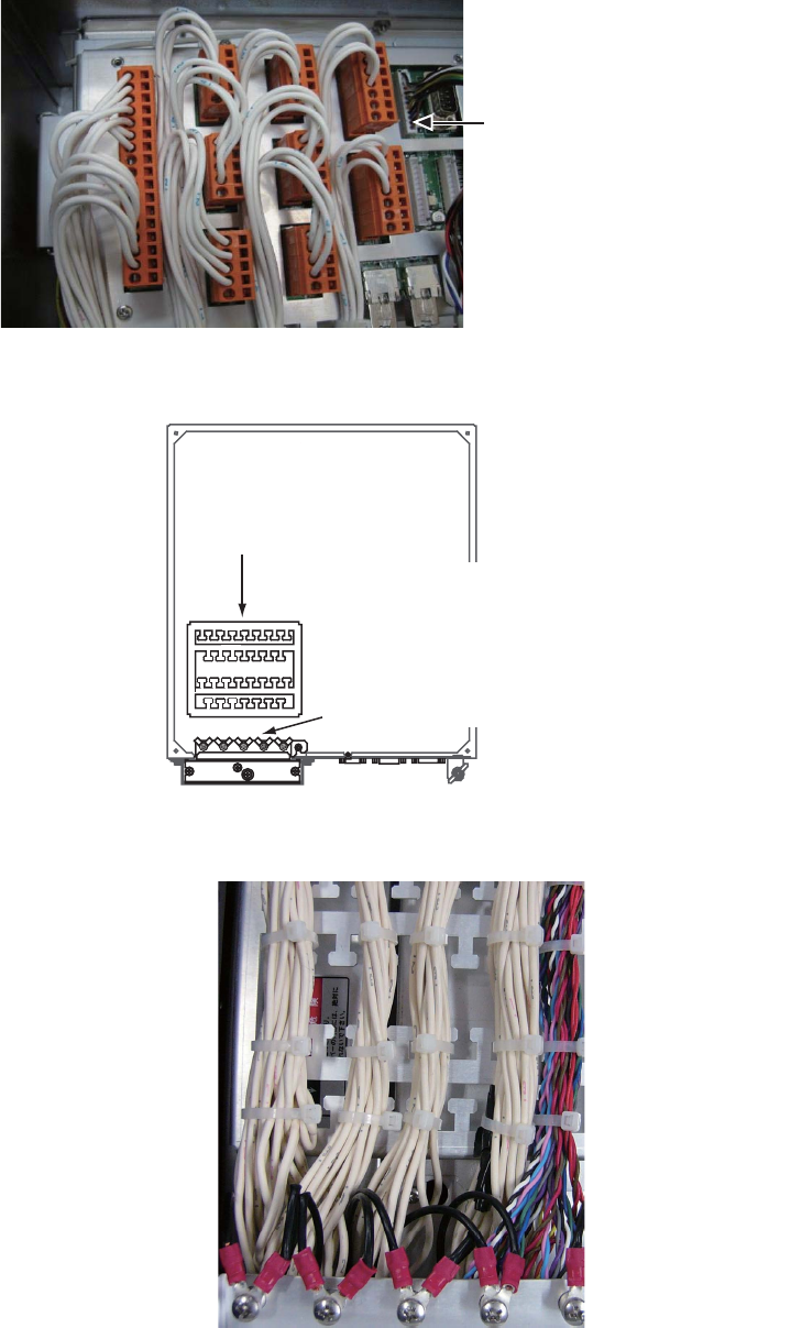
4. Connect the WAGO connectors appropriately to the I/O Board, referring to the in-
terconnection diagram.
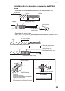
5. Bind the cables to the fixing metal in the processor unit with the cable ties (sup-
plied).
6. For TTYCSLA series cables, pass the drain wire into the shrink tube (local sup-
ply), then fasten crimp-on lugs at the end of drain wires to screws shown above.
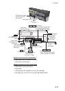
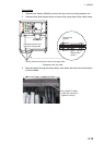
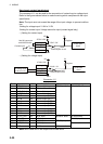
Example of wiring (inside the processor unit)
J12 (main control unit)
For J13 and J14 (sub
control units), see the figure
at step 2 on the previous page.
Fixing metal
Screws for drain wires
of TTYCSLA cables
(Pass the drain wires through
the shrink tubes (local supply),
then attach these crimp-on lugs
to the drain wire.)