


2. WIRING
2-38
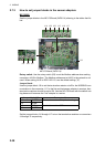
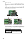
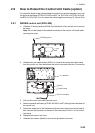
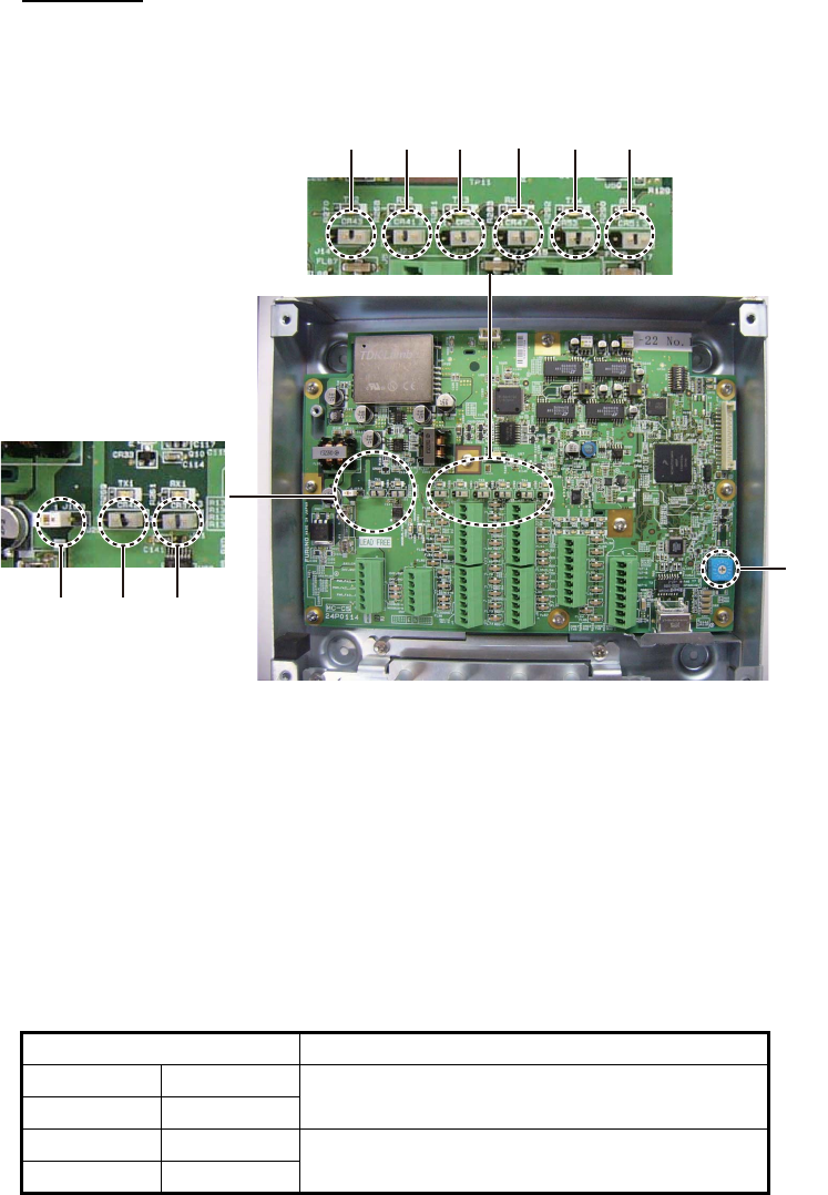
2.7.3 How to set jumper blocks in the sensor adapters
MC-3000S
See the jumper blocks in the MC-CS Board (24P0114) referring to the tables that fol-
low.
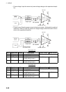
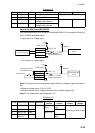
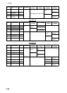
MC-CS Board (24P0114)
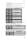
Rotary switch: Use the rotary switch (S2) to set the Modbus address when setting
connectors J4/J5 to Modbus. The Modbus address set at J4/J5 in the network is not
used. When setting J4/J5 to IEC61162-1/2, use the default setting (“0”).
Jumper block:
Use the jumper block J19 to set the termination resistor on/off for the MODBUS com-
munication on the connector J1. For the first and last sensor adapter in a series, their
termination resistors should be set to ON. Use the MC-CS Board with the default set-
ting because it becomes the “first” adapter in a series.
Set the jumper blocks J14 through J17 to turn the termination resistors on connectors
J4 through J7 respectively.
Jumper block J19 Connector J1
1-2 SHORT Termination resistor: ON (default setting)
2-3 OPEN
1-2 OPEN Termination resistor: OFF
2-3 SHORT
S2
J14
J22 J23 J15 J16 J17
J19 J20 J21