


2. WIRING
2-20
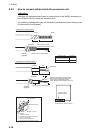
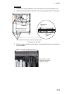
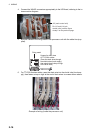
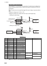
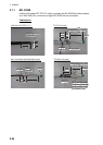
How to set contact input/output
The connector J11 can be used for the connection of contact input or voltage input.
Refer to the figures shown below to make the wiring which complies with the input
specification.
Note: The input must not exceed the range of the input voltage, to prevent malfunc-
tion.
-Setting for voltage input: 21.6V to 31.2V
-Setting for contact input: Voltage cannot be input (contact signal only).
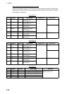
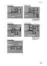
• (Setting for contact input)
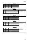
• (Setting for voltage input)
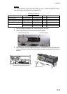
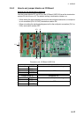
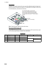
Connector J11
Note: NC1/2 and NO1/2 are output with a fixed value.
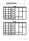
Pin # Signal name In/Out Description Contact input Voltage input
1 SYS_FAIL-A Out System fail output TTYCS(LA)-10 TTYCS(LA)-10
2 SYS_FAIL-B Out System fail output
3 PWR_FAIL-A Out Power fail output
4 PWR_FAIL-B Out Power fail output
5 NC1-A Out Alarm output (NC1)
6 NC1-B Out Alarm output (NC1)
7 NC2-A Out Alarm output (NC2)
8 NC2-B Out Alarm output (NC2)
9 NO1-A Out Alarm output (NO1)
10 NO1-B Out Alarm output (NO1)
11 NO2-A Out Alarm output (NO2)
12 NO2-B Out Alarm output (NO2)
13 DC12V_OUT Out ACK input #13-#14: short No connection
14 DIGI_IN1 In ACK input TTYCS(LA)-10
15 DIGI_RTN1 Out ACK input TTYCS(LA)-10
16 GND (DC12V) In ACK input No connection
17 GND - GND NO connection
GND
5V
12V
GND
to MC-DIN
circuit
470Ω/ 0.5W
2.2kΩ / 1W
Contact input
DC12V_OUT
DIGI_INx
DIGI_RTNx
GND(DC12V)
Photocoupler circuit
Register
Use NH connector
and AWG24 wire.
DC12V_OUT
DIGI_INx
DIGI_RTNx
GND(DC12V)
GND
5V
DC voltage input
(21.6V to 31.2V)
+
-
12V
GND
to MC-DIN
circuit
470Ω/ 0.5W
2.2kΩ / 1W
Photocoupler circuit
Register