


3-1
3. SETTING AND ADJUSTMENT
Note: After completing the settings and adjustments, copy the setting data to a USB
flash memory, referring to section 22.2 File Export in the Operator’s Manual.
3.1 Radar Setting
3.1.1 How to access to the installation manual
After completing the installation, press the MENU key five times while pressing the 1
HL OFF key down to show the [RADAR INSTALLATION] on the main menu.
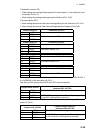
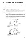
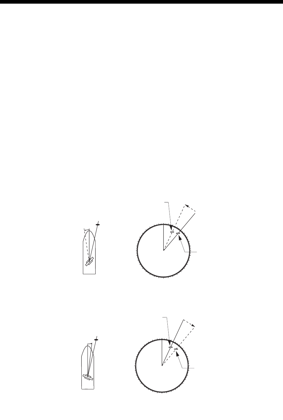
3.1.2 Heading alignment
You have mounted the antenna unit facing straight ahead in the direction of the bow.
Therefore, a small but conspicuous target dead ahead visually should appear on the
heading line (zero degrees).
In practice, you will probably observe some small bearing error on the display because
of the difficulty in achieving accurate initial positioning of the antenna unit. The follow-
ing adjustment will compensate for the error.
000
010
020
030
040
050
060
070
080
090
100
110
120
130
140
150
160
170
180
190
200
210
220
230
240
250
260
270
280
290
300
310
320
330
340
350
a
Target
a
Correct bearing
relative to heading
Antenna mounted error
to port (HDG SW
advance)
Picture appears
deviated clockwise.
000
010
020
030
040
050
060
070
080
090
100
110
120
130
140
150
160
170
180
190
200
210
220
230
240
250
260
270
280
290
300
310
320
330
340
350
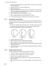
b
Target
b
Apparent position
of target
A
ntenna mounted error
to starboard (HDG
SW delayed)
Picture appears
deviated counterclockwise.
Correct
bearing
relative to
heading
Apparent
position
of target