


2. WIRING
2-32
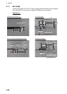
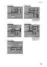
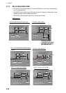
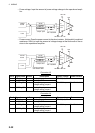
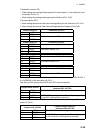
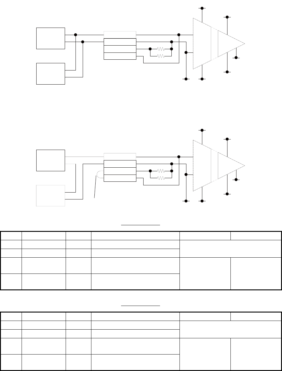
• Power voltage: Input the amount of power voltage change to the operational ampli-
fier.
• Power current: Pass the power current to the shunt resistor, 1kΩ/parallel (combined
resistance: 500Ω) to input the amount of voltage change at the both ends of the re-
sistor to the operational amplifier.
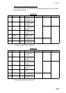
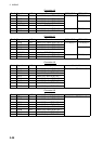
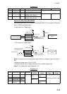
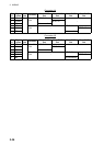
Connector J3
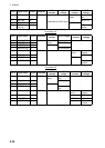
Connector J4
Pin # Signal name In/Out Description Power voltage Power current
1 AN1_IN In Analog 1 input TTYCS(LA)-1
2 AN1_GND - Analog 1 GND
3 CURR1_JP1 - Analog 1 input, power current/
voltage setting jumper 1
Pin #3-#4: open Pin #3-#4: short
4 CURR1_JP2 - Analog 2 input, power current/
voltage setting jumper 1
Pin # Signal name In/Out Description Power voltage Power current
1 AN2_IN In Analog 2 input TTYCS(LA)-1
2 AN2_GND - Analog 2 GND
3 CURR2_JP1 - Analog 2 input, power current/
voltage setting jumper 1
Pin #3-#4: open Pin #3-#4: short
4 CURR2_JP2 - Analog 2 input, power current/
voltage setting jumper 1
AN-IN
AN-GND
CURR-JP1
AN +15V
AN GND AN -15V
Opeamp
Vin
InGnd
+VS1
-VS1
+VS2
-VS2
OutGnd
+15V
GND
-15V
Voltage
source
Load
Jumper: open
1kΩ 1% 0.5Wx2
CURR-JP2
AN-IN
AN-GND
CURR-JP1
CURR-JP2
AN +15V
AN GND AN -15V
Opeamp
Vin
InGnd
+VS1
-VS1
+VS2
-VS2
OutGnd
+15V
GND
-15V
Current
source
Load
Jumper short
1kΩ 1% 0.5Wx2
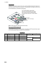
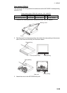
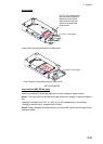
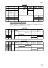
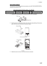
Use NH connector
and AWG24 cable.