


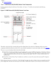
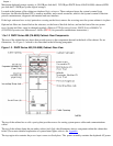
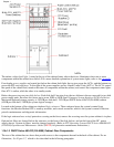
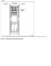
The amber cabinet fault light , located at the top of the cabinet frame, above the doors, illuminates when one or more
components within the cabinet have failed. (For a more detailed explanation of system status lights, refer to the Appendix.
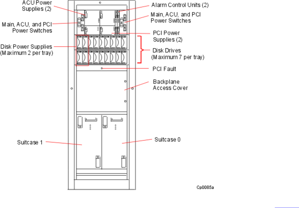
Four duplex power supplies are located just below the cabinet fault light: the top two power the ACUs, and the bottom two
power the PCI card cage bays. To the right of the power supplies are two Alarm Control Units (ACUs). The ACUs control
the speed of the cabinet fans, monitor the status of components within the cabinet, and control the component status lights.
One ACU is online, while the other is in standby mode.
Below the power trays are two disk shelves. Each disk shelf has nine slots, the two leftmost slots are reserved for two disk
power supply units, the other slots house up to seven 9GB or 18GB Small Computer System Interface (SCSI) disk drives.
Maximum duplexed storage capacity is 126 GB per disk shelf, 252 GB per DNCP Series 400-CO (PA-8500) cabinet
(63GB per disk shelf, 126GB per system logical storage).
Located at the bottom of the cabinet are duplexed logic suitcases. These suitcases house the system's central logic
functions: the Hewlett-Packard CPUs, memory modules, and console controller, which is the system's central collection
point for maintenance and diagnostic information.
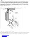
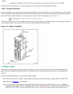
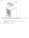
If the logic suitcases have a vinyl protective covering on the front, remove the covering once the system cabinet is in place.
Optional air filters are located below the suitcases, on the front of the disk shelves, and on the front of the DC power
supply chassis. System air filters must be changed regularly. (Refer to FTX Operating System: DNCP Series 400/400-CO
(PA-8500) Operation and Maintenance Guide (RXXX) for preventive maintenance instructions.)
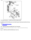
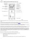
1.3b.1.2 DNCP Series 400-CO (PA-8500) Cabinet: Rear Components
The rear of the cabinet has two doors that provide access to the components housed in the back of the cabinet. For an
illustration, See Figure 1.7, which is also described in the following paragraphs.
Chapter 1