


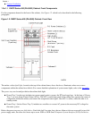
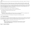
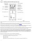
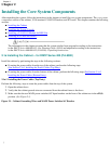
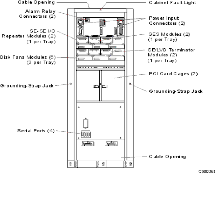
Figure 1.7. DNCP Series 400-CO (PA-8500) Cabinet: Rear View
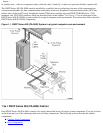
The top of the cabinet has a cable opening that provides access for routing system power cables and communications
cables.
The top of the cabinet frame has an amber cabinet fault light that illuminates when a component within the cabinet has
failed. (For a more detailed explanation of system status lights, refer to the Appendix
The top region also contains the power input connectors for the duplexed DC power cables, and the alarm relay connector
for remote alarm monitoring. Each power cable requires a separate -48V nominal DC electrical source.
Below the power input region (DC power chassis) are two disk shelves which each contain three cooling fans, a SES (SCSI
Enclosure Services) unit, a SE-SE (single-ended to single-ended) I/O repeater module and a terminator module.
Below the disk shelves are two PCI card cages. Each card cage contains seven slots for PCI cards, for a total of 14 PCI
cards per system. See the PCI-card installation manual for detailed information about a specific PCI card. Each PCI card
cage has one bridge card that provides the interface between the logic suitcases and the PCI cards. Each bridge card has a
connector for a PC Memory Card International Association (PCMCIA) flash card, a credit-card-sized EEPROM used to
boot the operating system.
Beside each of the PCI card cages is a jack for attaching a grounding strap.
Four serial ports at the bottom of the cabinet are used to connect the system to the:
CPU/memory motherboard within each logic suitcase
●
system console●
remote console●
Remote Service Network (RSN) modem (Not all systems are connected to the RSN. For an●
Chapter 1
]