


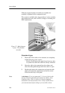
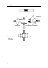

Cable layout
169
857-164342 / Rev.C
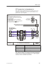
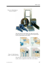
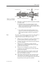
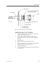
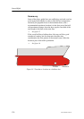
Figure 13 Standard
cable gland assembly
Compression nut
Cable
Gland body
Cabinet panel
Screen collarCompression seal
Screen
(CD3260)
4 Depending on whether the cable has already been installed
in conduits, either:
h (installed) measure the maximum length of cable
required to reach from the final cable clip outside the
cabinet to the terminal blocks inside the cabinet, add 20
cm, then remove the excess cable,
or:
i (loose cable) measure the maximum length of wire
required to reach from the cable gland to the terminal
blocks inside the cabinet, add 20 cm. and mark the
cable.
Note The cable’s outer insulation will extend into the cable gland to a
point approximately 5 mm outside the outer surface of the
cabinet wall into which the cable gland is secured.
5 Taking care not to damage the screening, carefully remove
the outer insulation from the required cable length.
6 Leaving 12 mm of the screen exposed from the insulation,
cut off the remainder.
7 Taking care not to damage the screening, slide the
compression nut (smallest diameter first) over the cable
and onto the intact insulation.
8 Taking care not to damage the screening, slide the
compression seal (rounded end first) over the cable and
onto the intact insulation.
9 Slide the screen collar (narrow end first) onto the cable
and fit it underneath the screen. Slide it as close to the
intact outer insulation as possible.
10 If the screen extends beyond the “flat” end of the screen
collar, fold any excess length over the end of the collar
such that the screen will be gripped between the collar and
the gland body when the parts are assembled.