


Conveying System Mechanical Components Chapter 2: Functional Description 15 of 138
Chapter 2: Functional Description
2-1 Models Covered in This Manual
This manual provides operation, installation, and maintenance instructions for the mechanical
components of the conveying system. Model numbers are listed on the serial tag. Make sure
you know the model and serial number of your equipment before contacting the manufacturer
for parts or service.
Our mechanical components are designed to create vacuum for conveying pelletized,
granular, or powder material in a central material handling system. A typical use is as an in-
plant distribution system for plastic processing plants. Conveying system mechanical
components are sized to meet the specific requirements stated by the Customer at the time of
purchase.
2-2 General Description
Our central vacuum systems are as varied as the applications that they service. Tubing and
equipment furnished in a specially designed system is intended to convey the material(s)
specified at the time of purchase at specific rates and distances.
We can advise you on your system capabilities based on system makeup, distance, material,
and desired conveying rates.
Pressure drops in the overall system directly affect system capacity, such as number of
material line bends, footage of pipe, Y-tubes, T-tubes, etc.
The less distance, flexible hose, and bends you use on material lines, the better. Keep material
lines as straight as possible.
Note: Vacuum leaks occurring anywhere in your system reduce capacity.
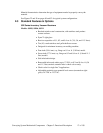
Basic System Components
A typical conveying system contains the following components:
• Vacuum receiver(s)
• Vacuum pump
• Filter chamber
• Sequence or atmospheric valves
• Controller
• Take-off compartments
• Pickup tubes/wands
• Vacuum and material tubing
Combinations of these components will help you build your system for the application you
need.