Conveying System Mechanical Components Chapter 4: Operation 79 of 138
Chapter 4: Operation
4-1 Start-up
Starting ACA Series Filter Chamber Units
Turn on clean, dry, oil-free compressed air and regulate to 60 psi to 80 psi (414 kPa to 552
kPa). Turn the power on/off switch to ON; the unit then automatically self-cleans the filter
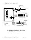
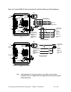
bags. An indicator light on the control box for Model 91/93, 151/153, and 251/253 ACA filter
chambers illuminates each time a compressed air pulse is directed into a filter bag.
Note: If for any reason the power is turned off, wa
it at least three (3) seconds to reset.
4-2 Operation Procedures
When you activate the controller, the system energizes and initiates the conveying cycle. The
following components energize:
• The vacuum pump motor starter.
• The vacuum pump vent valve.
• The sequencing valve above the first on-line vacuum receiver that
requires material.
The vacuum pump draws vacuum to that receiver. When the receiver is full or the time
interval elapses, the controller then signals the atmospheric valve above the next on-line
receiver requiring material to energize, allowing material to convey to that receiver. The
conveying sequence continues to the last on-line vacuum receiver requiring material.
When the time interval for the last receiver elapses or the receiver is full, a new conveying
cycle begins at the first on-line vacuum receiver requiring material.
Note: The sequence of events listed above is a generalized description of what occurs
when a controller is activated. Consult your specific controller manual for an
accurate depiction of these events.
Vacuum Switch (VS) Operation
A high vacuum switch is mounted inside a pump package junction box. It is preset to close at
14” Hg (475 millibars) and is not adjustable. The vacuum switch protects the pump package
from motor damage caused by high amperage draw and strain on the blower.
Pumps typically draw a vacuum of less than 5” Hg (170 millibars) only when air is pulled
into the system and 8” to 12” Hg (271 to 339 millibars) while conveying.
If system vacuum should reach 14” Hg (475 millibars), the high vacuum switch closes. The
pump package tries to clear the line for three seconds, then moves to the next on-line vacuum
receiver. The normal conveying cycle continues. If high vacuum keeps occurring, the pump
continues with attempts to clear the line.
See your specific controller manual for additional operation information.


