


Conveying System Mechanical Components Chapter 3: Installation 70 of 138
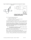
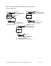
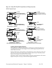
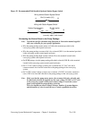
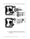
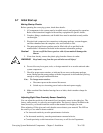
Figure 35: Recommended Field-Installed Optional Station Bypass Switch
A B
Wiring without Station Bypass Switch
Bin-Full switch (LS)
N. O.
(normally open, held closed)
A1
B
A
Wiring with Station Bypass Switch
Station Bypass switch
(TS)
Off
On
Bin-Full switch
(LS)
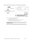
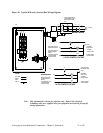
Connecting the Control Panel to the Pump Package
Note: Consult the specific schematics and Operation & Instruction manual supplied
with your controller for your specific application.
• Wire the pump package motor starter coil (M) to the terminal provided in the
conveying system control panel enclosure.
• Wire the pump package vacuum relief valve solenoid (SOL A) to the terminal provided
in the conveying system control panel enclosure.
• Wire the pump package high vacuum switch (VS) to the terminal located in the
conveying system control panel enclosure.
• On SPDB pumps, wire the pump package blowback solenoid (SOL B) to the terminal
located in the conveying system control panel enclosure.
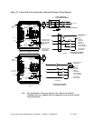
• On 115 VAC control voltage systems, run a common hot 115 VAC wire and a
common neutral wire from the controller to the pump package in the conveying
system.
• On 24 VDC control voltage systems, run a common +24 VDC wire and a common 0
(zero) VDC wire from the controller to the pump package in the conveying system.
Note: Make sure that the pump motor starter, the vacuum relief valve solenoid, and
the blowback solenoid (if supplied) are the same voltage (24 VDC or 115 VAC)
as the conveying system control panel control voltage. Consult the control
panel serial tag and the pump package serial tag.
Wire size depends on control voltage, distance, number of vacuum hoppers,
and the number of wires in each raceway. Consult a qualified electrician.