


Conveying System Mechanical Components Chapter 3: Installation 73 of 138
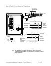
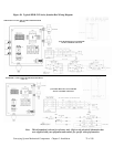
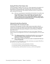
SUB PANEL LAYOUT AND CONNECTION DIAGRAM
(24V DC)
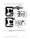
Note: This information is shown for reference only. Refer to the electrical Schematics that
were supplied with your equipment and controls for specific wiring information.
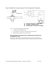
Figure 38: Typical SPDB 5-15 Series Junction Box Wiring Diagram
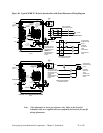
JUNCTION BOX ON VACUUM PUMP
24V DC CONTROL VOLTAGE
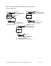
SUB PANEL LAYOUT AND CONNECTION DIAGRAM
(115V AC)
JUNCTION BOX ON VACUUM PUMP
24V DC CONTROL VOLTAGE